|
|
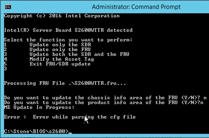
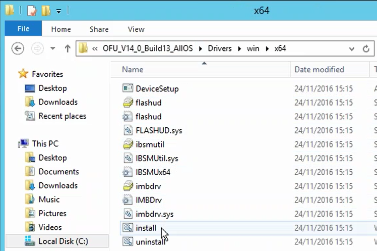
ProblemWhen you try and update the BIOS in Windows using the Intel OFU program ("One Boot Flash Update") tool, you get an error message saying that there was an "Error while parsing the cfg file". CauseThis issue is caused by an out of date IPMB driver being installed in Windows. Typically an out of date IPMB driver might be in use if an older SELVIEWER, SYSINFO or Intel Active System Console has been installed or used previously. ResolutionThe Intel OFU BIOS Update utility can only run when an up to date IPMI/IPMB driver is installed. The OFU package contains an updated IPMI driver. Instructions
Note: No reboot is normally required in between installing, or upgrading the IPMI driver and flashing the BIOS.
Applies to:
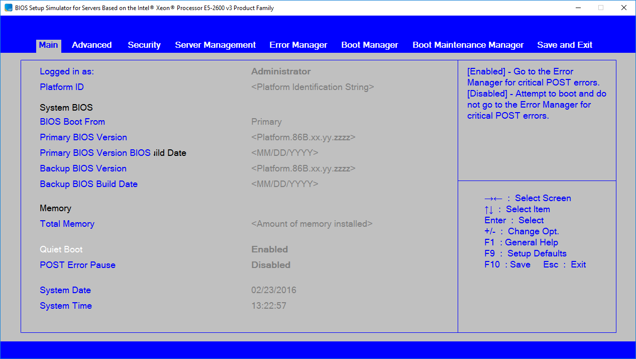
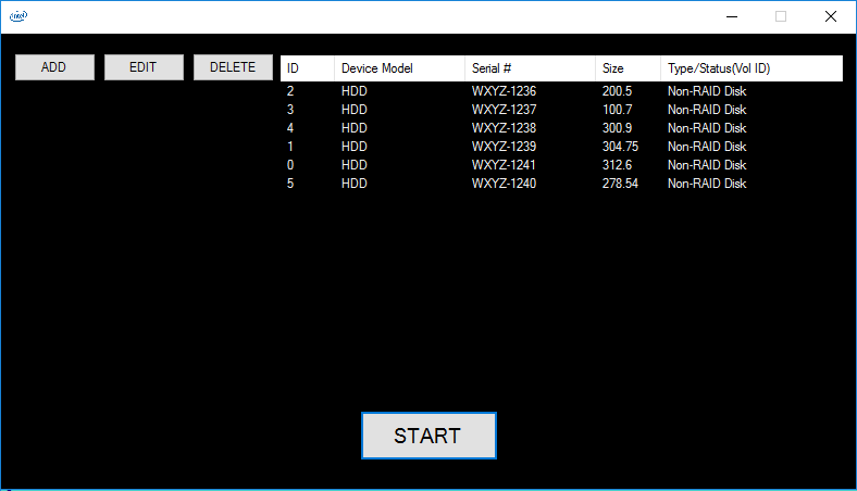
BIOS SimulatorPlease find below a link to the Intel BIOS simulator for server systems. This is an updated similator for the Xeon Processor E5-2600 v3 Product Family, including S2600WTT, S2600CP2 and S2600CP4. This utility simulates the BIOS interface a user would normally see when pressing <F2> during POST. It can be used for support or research purposes. Note: Use the Intel download link to obtain the latest version of this simulator.
Downloads
Required Component for the Simluator To Run: Microsoft Visual Basic PowerPacks 10.0
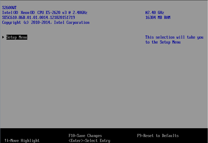
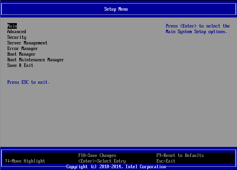
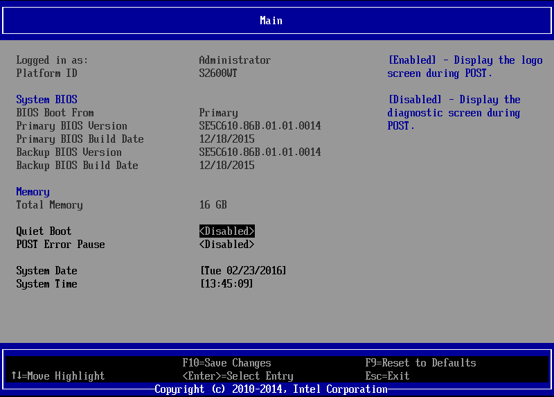
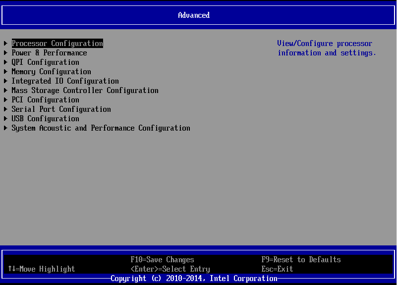
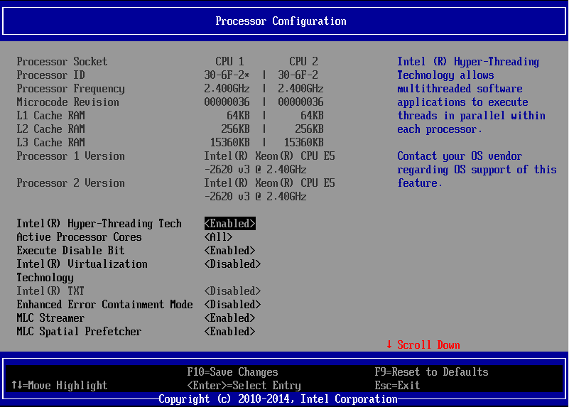
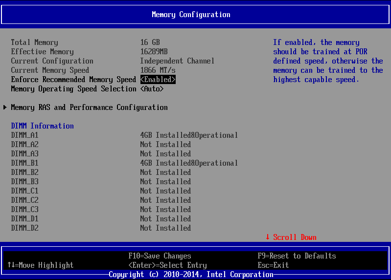
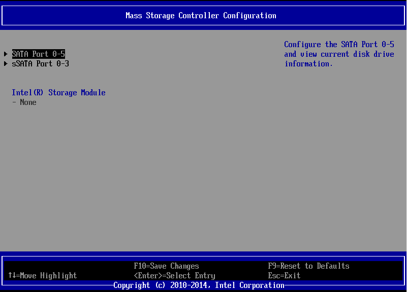
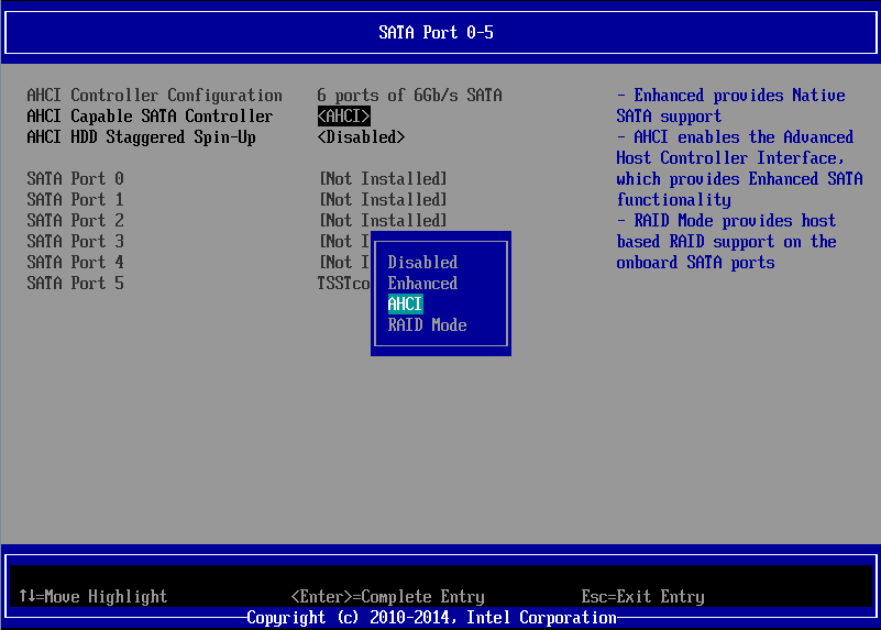
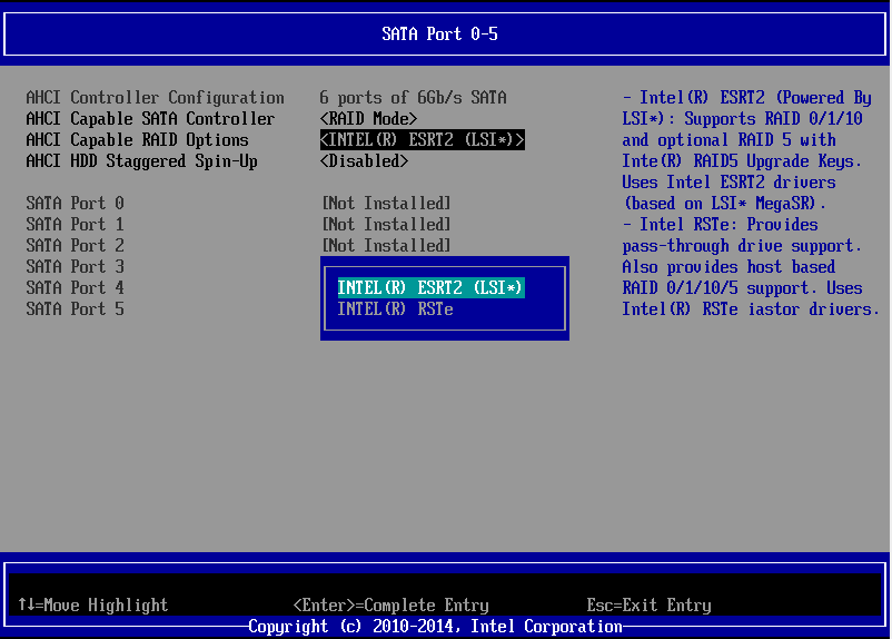
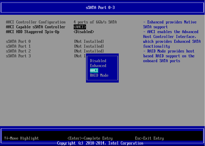
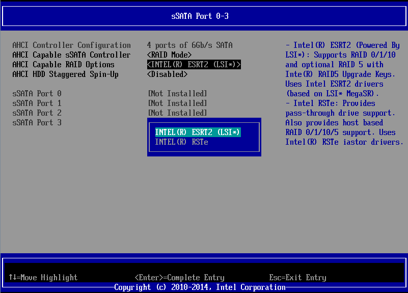
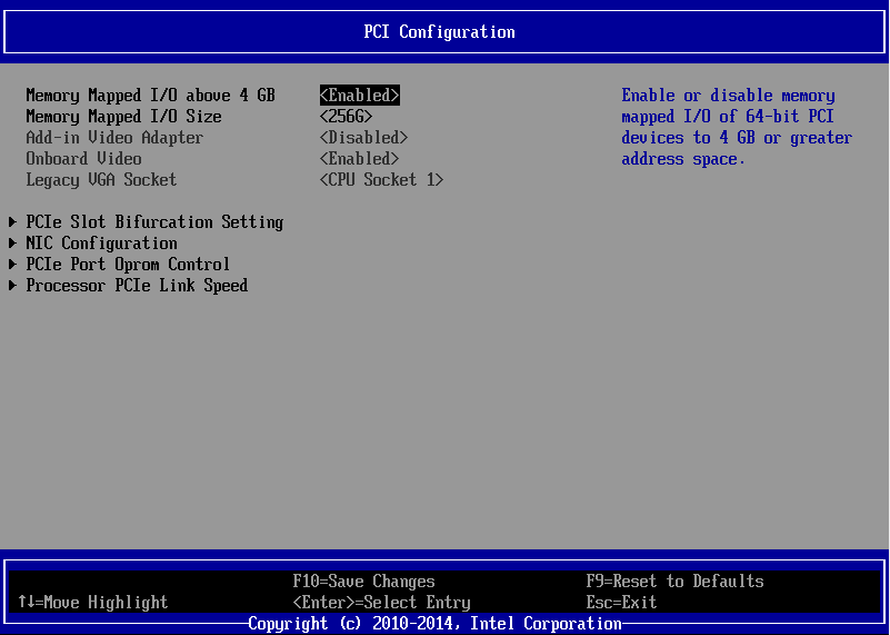
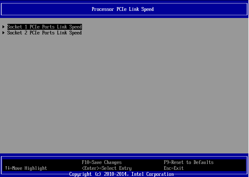
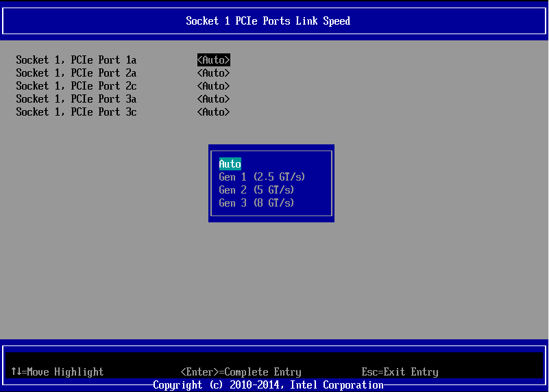
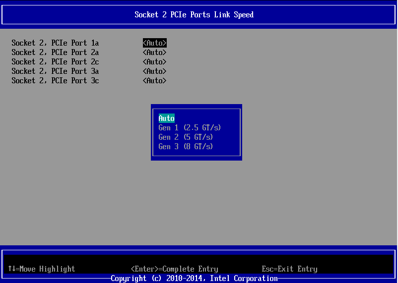
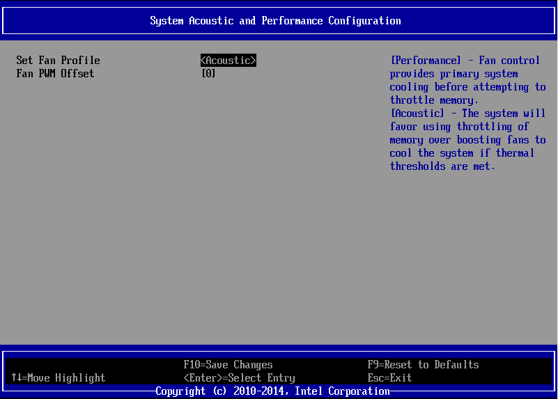
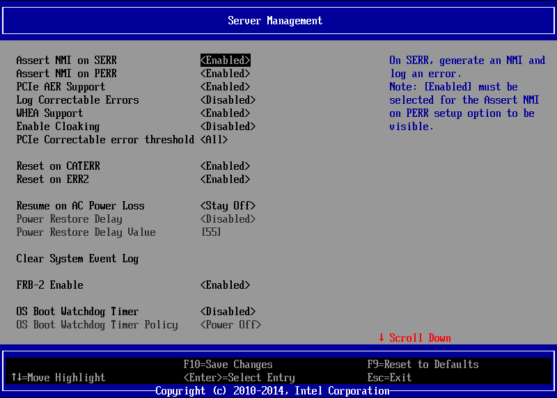
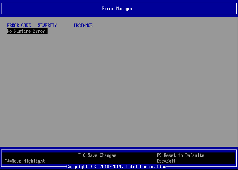
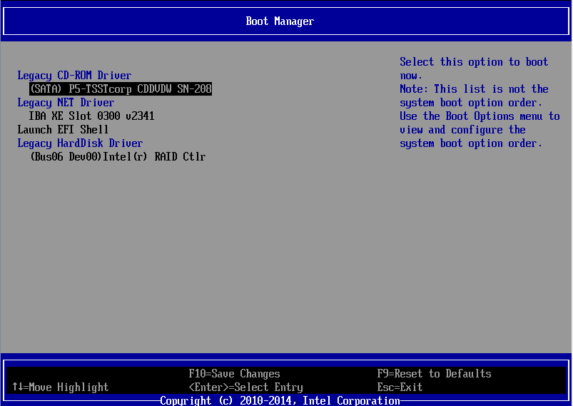
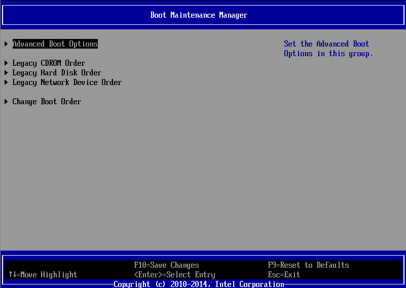
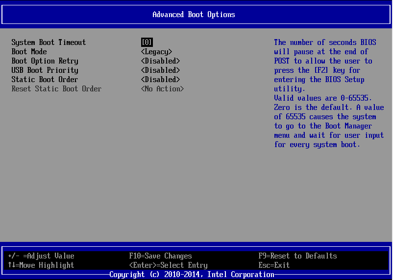
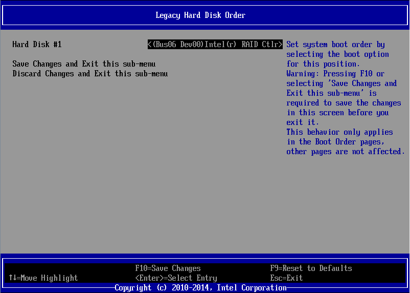
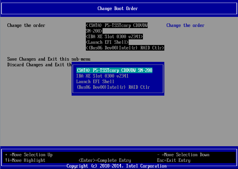
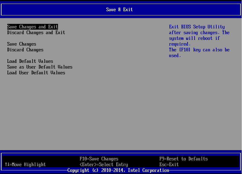
Differences Between the Simulator and the ProductWhilst the simulator shows you the common options available on the S2600 v3 platform, there are some differences in the latest versions of the BIOS. The S2600WT example is shown below. BIOS ScreenshotsThe screenshots below are taken from the S2600WT but broadly apply to the S2600WTT, S2600CP2, S2600CP4 and S2600CW2. Pressing F2 on POST Brings you to a Pre-Setup Screen Inside the Setup Menu, Most BIOS tabs are now listed top down, instead of across the top Start > MAIN Start > Advanced Start > Advanced > Processor Configuration Start > Advanced > Memory Configuration Start > Advanced > Mass Storage Controller Configuration Start > Advanced > Mass Storage Controller Configuration > SATA Port 0-5 Start > Advanced > Mass Storage Controller Configuration > sSATA Port 0-3 Start > Advanced > PCI Configuration Start > Advanced > PCI Configuration > Processor PCIe Link Speed Start > Advanced > PCI Configuration > Processor PCIe Link Speed > Socket 1 Start > Advanced > PCI Configuration > Processor PCIe Link Speed > Socket 2 [Where fitted] Start > Advanced > System Acoustic and Performance Configuration Start > Server Management Start > Error Manager Start > Boot Manager Start > Boot Maintenance Manager Start > Boot Maintenance Manager > Advanced Boot Options Start > Boot Maintenance Manager > Legacy Hard Disk Order Start > Boot Maintenance Manager > Change Boot Order Start > Boot Maintenance Manager > Change Boot Order > (Item Selected) Start > Save & Exit Applies to:
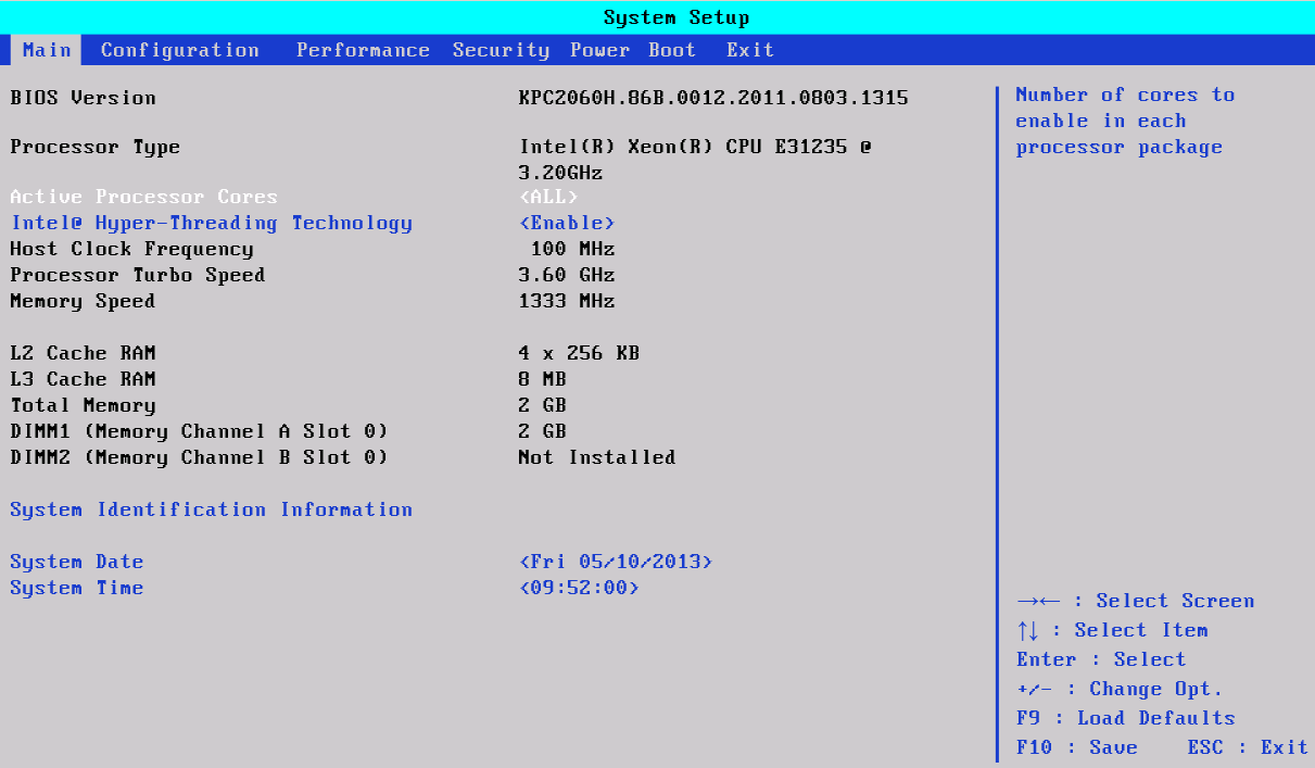
Please find below a link to the Intel BIOS simulator for S1200KP server systems. This utility simulates the BIOS interface a user would normally see when pressing <F2> during POST. It can be used for support or research purposes. Note: Use the Intel download link to obtain the latest version of this simulator.
Downloads
Applies to:
Please find below a link to the Intel BIOS simulator for server systems. This utility simulates the BIOS interface a user would normally see when pressing <F2> during POST. It can be used for support or research purposes. Note: Use the Intel download link to obtain the latest version of this simulator.
Downloads
Applies to:
The Hardware System Event Log (SEL) - IntroductionThe hardware SEL is a function of most server motherboards. The baseboard management controller (BMC) records hardware events, including most health events, into an area of the motherboard non-volatile memory. In other words, this event log can be retrieved even after the system has been cold booted. A CMOS clear is likely to delete all of the events. The hardware SEL should not be confused with the Windows System event log, which records Windows events. The hardware SEL will record things such as power events (power on, power off/loss of power, power redundancy events etc.) and faults such as fan issues, memory ECC events, or some motherboard errors such as PCI Express bus faults. Choosing the right method of retrieving the SEL informationMotherboard manufacturers such as Intel provide utilities to display or save the SEL log. Utilities available depend on the motherboard model. Use the DOS or EFI mode version when Windows is not operating. For most models, a Windows version is available which allows SEL events to be retrieved while Windows is running, after the installation of an IPMI management driver. While DOS mode tools are available for some platforms, use of EFI tools is preferred as you do not need to prepare a Windows 98SE DOS bootable pen drive. Methods available for retrieving the SEL informationYou will need to download the SEL viewer utility for either EFI, DOS or Windows. Always consult the motherboard or platform download pages for updated downloads. Tip: In addition to the SEL Viewer utilities for EFI or Windows, the latest range of boards and systems from Intel now also support the SysInfo tool. The Sysinfo tool works in a very similar way but records even more information, at the cost of taking slightly longer to run.
On all Windows systems you need to install the correct package (32-bit / 64-bit) in order to install the correct IPMI driver. The IPMI drivers are included in the distributions. Note that the Window's SEL log utility requires Java to be installed if you want the GUI displayed. Using the command line option to save the log does not require Java. Note: If you install the Windows 64-bit version on a 64-bit capable system but the SEL viewer GUI fails to run, it may be because you either dont have any Java installed, or you only have 32-bit Java installed. It is possible to install the 64-bit IPMI driver and then use the 32-bit SELVIEWER utility with 32-bit Java installed.
Applies to:
The EFI ShellThe Extensible Firmware Interface (EFI) shell is effectively a small operating system built into the system motherboard on modern servers. This provides an environment for troubleshooting and maintenance outside of the operating system. This article describes how to access the EFI shell on an Intel Server or Workstation board and how to access resources on a USB pen drive. Reminder: EFI tools can only be used when the main operating system is not running. If you are not in a postition to be able to down the server, use operating system tools instead. For example, for Windows based systems, Windows versions of the Hardware System Event Log (SEL) viewer are available, as are Intel / LSI RAID management and firmware upgrade tools.
How to Access Tools through the EFI ShellGeneric instructions are provided below. Exact screens and steps may vary from model to model.
Note: Generally most FAT16 or FAT32 formatted USB pen drives will work on servers in the EFI shell, even USB3 models on USB2.0 only servers. However, add-on USB3.0 controller cards (such as those added to some workstations) may not be detected in the EFI shell. Try the front USB ports first, and then try the system onboard rear ports second.
Tip: Just as in DOS, use the TAB key to help auto-complete filenames. For example, type in "CD " and then use the tab key to step through the filenames available in the current directory.
Important: Some updates, such as RAID card firmware packages, will not run inside the EFI shell on older S5000 based systems. This is because these updates require EFI 2.0 which is not present on the S5000. In this instance, obtain the DOS version of the update and use a Windows 98SE DOS Bootable pen drive.
A seperate article wil cover using the SELVIEW utility in both EFI and Windows environments. Applies to:
Bootable Pen Drive There are many instances where a "DOS" or Windows 98SE bootable pen drive is required - for example, some BIOS updates or other low level updates can only be done in this way. (Stone is working to provide Windows update utilties wherever possible, but these arent always available yet). If you need to create a DOS or Windows 98SE (or FreeDOS) bootable equivalent, please see some links to third party sites below which host various solutions. Note: We are not responsible for the content of third party web sites
Rufus - http://rufus.akeo.ie/ HP USB Format Tool - Download here Windows 98 Boot files - here Applies to:
IssueEntry-level servers that use basic Serial-ATA hard drives may experience slow disk transfers if the server is a Microsoft Windows Domain Controller (DC). Typically file transfers to the server over the network are slow (around 10MB/second or less). File transfers between hard drives or partitions on the actual server itself are also slow. Hard Drive Caching Features Disabled by DesignThis issue is caused by the deliberate disabling of hard drive caching features on any system that is a domain controller. A Windows Domain Controller will attempt to disable hard drive caching features on every boot. Typically Windows cannot succeed in disabling caching features on systems equipped with a full hardware RAID controller, but it can succeed in disable caching features on systems equipped with single SATA hard drive. Note: This issue exists as Windows is operating in the way designed by Microsoft, so we cannot recommend that you work-around this issue. Hard drive caching features are disabled so as to guarantee the consistency of the Active Directory (AD) database, especially in the event of an unexpected power outage. We have provided a work-around below for customers that specifically require this, but recommend instead that customers use seperate domain controller and file/print physical servers. Use of the work-around is the customer's responsibility.
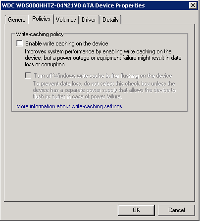
Re-Enabling Hard Drive caching FeaturesThis setting is visible in Device Manager of the affected system, however on every system boot the features will be disabled again. Both check boxes need to be ticked to restore maximum performance. (The default on any non-Domain Controller system is that at least the top check box is ticked). To re-enable full hard drive caching features on every boot, use the attached package.
Both fixes use the same utility but with different options. They are both usable on 2008R2 and 2012R2. However the 2012R2 version has been configured to enable caching features on all disks, including SCSI disks. This is needed on modern 2012R2 servers as most IDE or SATA disks now work through AHCI controllers which often, when the right driver has been loaded, appear as SCSI disks to the system. The 2008R2 fix only configures disks that are not recognised as SCSI to the system. Instructions
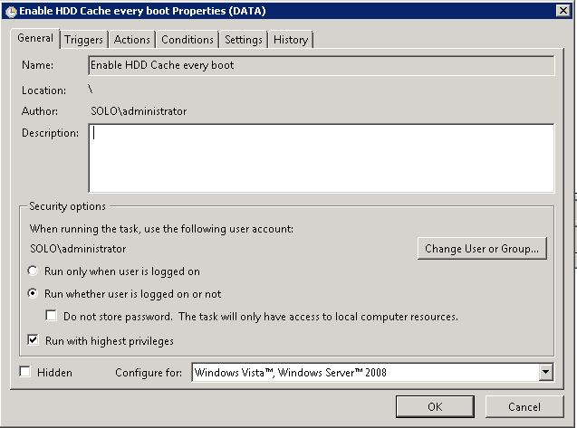
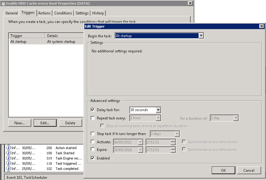
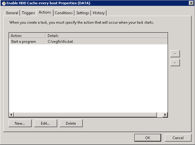
The package includes an importable Task Scheduler XML file; however you will need to change the task privledges and use your own Administrator username and password. If you want to use this XML file, you will need to extract the contents of the package to C:\Regfix
Reminder: It is recommended to use seperate physical hardware for Domain Controller and File and Print services to work-around this issue, unless using a virtualised environment. This work-around is provided for customers that need to resolve this issue and is provided without warranty. Customers must always ensure that servers are protected by a UPS and that they have tested system backups which include the System State / Active Directory database.
Applies to:
ProblemWhen you install Windows 7 or Windows Server 2008R2 on affected platforms the system performance can be noticeably poor. The mouse cursor is slow to respond; the system appears to be busy or have high CPU usage, and screen updates can be slow. Affected SystemsSystems affected include:
CauseThe root cause is the Microsoft provided Intel LAN controller driver which ships with Windows 7 and Windows Server 2008R2. This driver does not properly support the controller and it will cause the above symptoms. ResolutionUpdate the driver with the latest Intel LAN driver available from the Stone driver finder or Intel website. Updating the driver will restore the lost performance and also add the additional features provided by the full Intel LAN driver package. The LAN driver for these systems should be date 2011 or newer, as opposed to the Microsoft 2009 in box driver. Additional: On rare occasions we have seen system hangs during Windows setup, again because of this issue. If you encounter a system hang whilst installing Windows, disconnect the system from the network and then use a patch cable to connect both LAN adapters together. Then, attempt to install Windows again. When installed, then update the LAN driver as above.
Applies to:
How To Get A List of All Drives and Drive Health in Storage Spaces or Storage Spaces Direct (S2D) PoolExisting ToolsWindows Server already gives you a number of ways of looking at physical disk health:
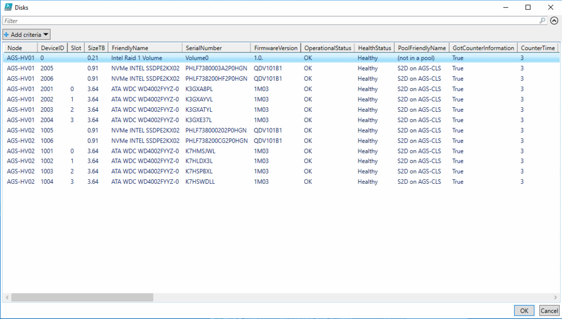
However none of these tools give an easy way of looking at all of the disk health across nodes in an S2D cluster and storage pools, in an easy to use, single pane of glass. To do this, use the attached S2D-DiskInformaton
Instructions
Output
Applies to:
The Intel S5000 based servers and workstations do not have an EFI based SELVIEWER tool. If Windows is not running, you need to use the DOS based tool in order to gather the hardware System Event Log (SEL). 1. Download the correct tool - here or here - for your S5000PSL, S5000PAL, or S5000XVN system. 2. Format a USB pen with the FAT32 file system. Make it bootable. To do this you will need a copy of the Windows 98SE boot files and a copy of the USB Format tool here or here (3rd party site). 3. Extract the DOS Selviewer download to the pen drive. 4. Boot the server from the pen drive. If necessary, go into the BIOS using the F2 key, and use the Boot Manager screen to directly boot from the pen drive. 5. When you have the DOS prompt, either run SELVIEW to lauch the GUI (which will allow you to save entries) or type in SELVIEW sn.sel /save to save a copy of the log entries directly to a file. 6. Send a copy of the file to Stone support for analysis. Note: Use a different filename from SN.SEL, such as the machines actual serial number, if you are dealing with multiple servers. You can examine SEL files by using Wordpad or Notepad to open them.
Applies to:
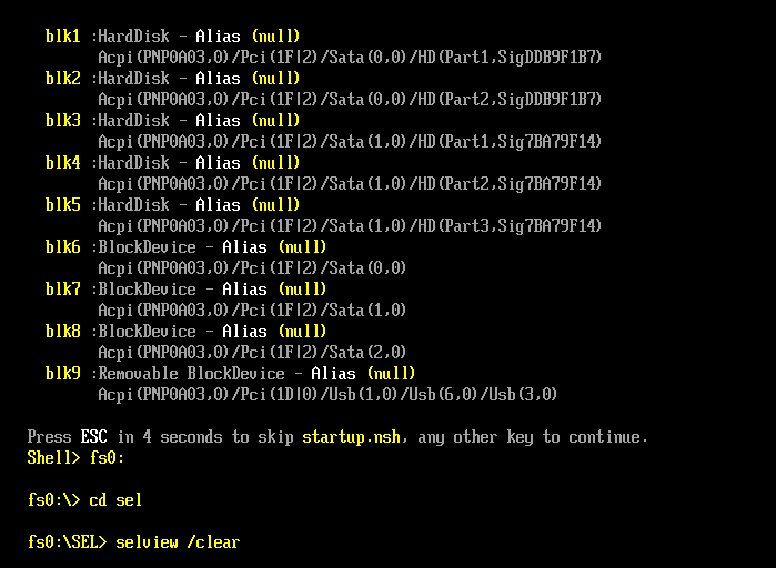
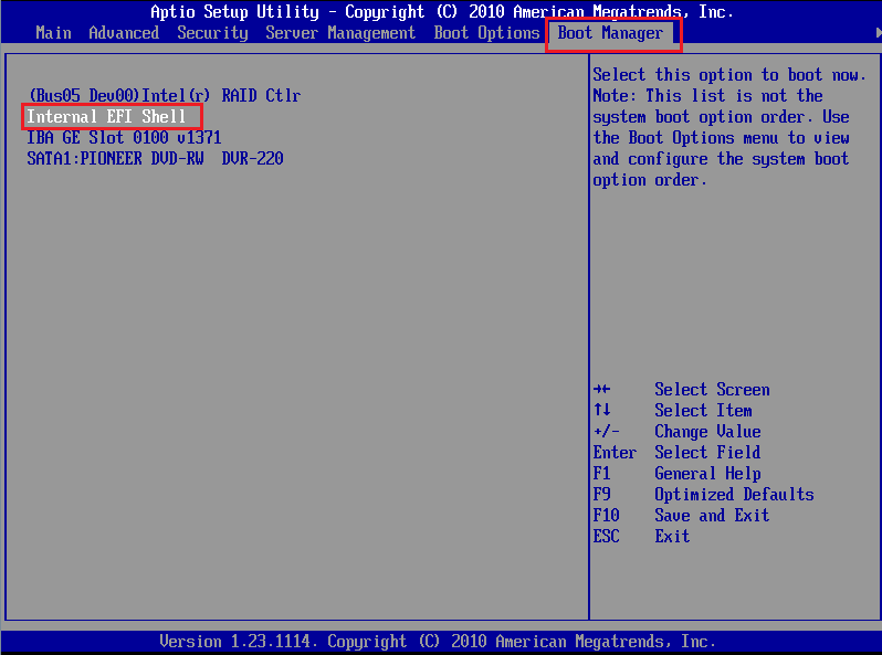
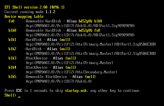
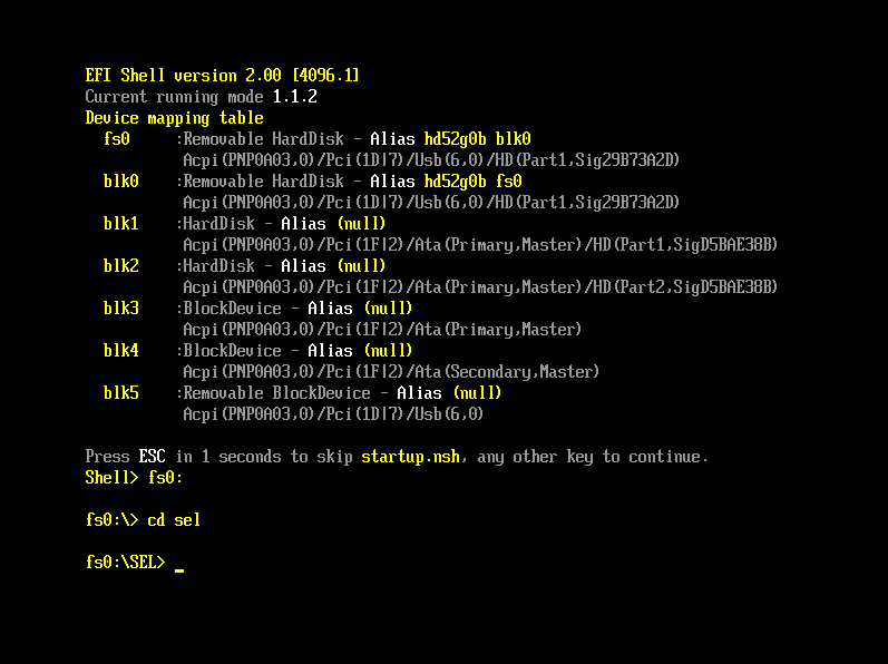
Short Instructions1. Download the EFI SEL Viewer and extract it to a FAT32 formatted USB pen drive. Connect the pen drive to the system while it is powered off. 2. Boot the server into the EFI Shell by using the F2 key during POST to go into the BIOS and then by using the Boot Manager screen to access the Internal EFI Shell 3. Change drive to the pen drive by typing in fs0: and then Enter. Change to the folder that you extracted the SELVIEW program to by using the cd command. 4. Run the SELVIEW program to run the GUI or run selview /save sn.sel to save the event log entries to a file. 5. Send the log file to Stone support for analysis. 6. If you need to clear the SEL Log of all entries, use selview /clear Detailed InstructionsThese instructions involve using the EFI shell for diagnostics. This can only be performed when the operating system such as Windows or ESXi is not running. If you need a Windows based tool, this is also available. 1. Download the EFI SELVIEWER tool for your motherboard or server platform. Many downloads contain tools for EFI and Windows, in which case find the folder which references UEFI: 2. Create a folder called SEL on a FAT32 formatted USB pen drive 3. Copy the SEL Viewer files to the SEL folder on the USB pen drive
4. Boot the system into the EFI Shell and follow the instructions to get to the fs0: prompt. 5.Use the cd command to change to the SEL directory.
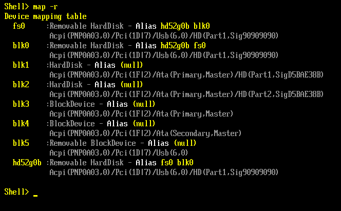
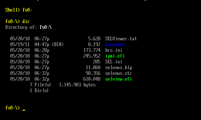
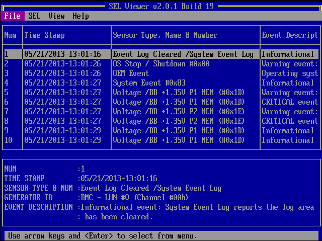
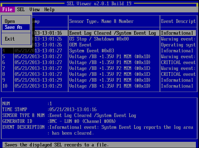
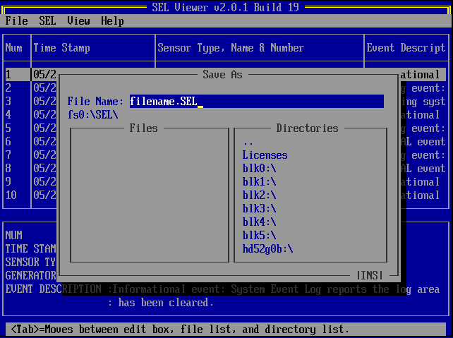
(6. Optional - use the DIR command to list files. Executables are highlighted in bright green). 7. To run the SEL Viewer and just save the log entries to a file on the pen drive, without opening the GUI, type in: selview /save sn.sel And press Enter. Replace sn.sel with the serial number of the system. 8. To run the SEL Viewer GUI, just type in selview and press enter. 9. To save the event log to a file using the GUI, do the following:
10. When you have saved a copy of the SEL Log to the pen drive, reboot the system. 11. Send the SEL text file into Stone support for analysis. 12. If you need to clear the SEL Log of all entries, use selview /clear Tip: In addition to the SEL Viewer utilities for EFI or Windows, the S1400, S1600, S2400 and S2600 range of boards and systems from Intel now also support the SysInfo tool. The Sysinfo tool works in a very similar way but records even more information, at the cost of taking slighly longer to run.
Applies to:
Instructions for the Windows Based Selviewer ToolThe Windows based Selviewer does not normally require rebooting to get the hardware log files, making it a useful tool. The instructions below are a guide as there are different versions of the Windows Selview tool and some of them look slightly different, or the filenames may vary. Tip: In addition to the SEL Viewer utilities for EFI or Windows, the S1400, S1600, S2400 and S2600 range of boards and systems from Intel now also support the SysInfo tool. The Sysinfo tool works in a very similar way but records even more information, at the cost of taking slighly longer to run.
Main Components
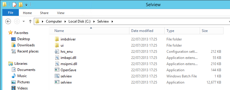
Quick Instructions - No User interface (recommended for System Admins or experienced users)1. Download the Windows Based SELVIEWER Tool for your platform and extract it. 2. Go into the extracted Selview folder, and then into the x64 or x86 subfolder, depending on your operating system. Copy the contents of this x86 or x64 folder to C:\SELVIEW or another easy to type location. You should end up with the following: 3. Open an Administrative command prompt and use the CD command to go to C:\SELVIEW\IMBDRIVER 4. Install the IPMI driver, usually using the command INSTALL C:\SELVIEW\IMBDRIVER 5. Some version of Selviewer require Java if you plan to use the full interface. As these instructions cover quick usage without the user interface, Java is not required to be installed. 6. Using the Administrative command prompt, go to the folder containing Selview.EXE (use the corresponding sub-folder x86 or x64 depending on if your operating system is 32-bit or 64-bit). 7. Run SELVIEW.EXE sn.sel /save to save a copy of the events. 8. Send the output file to Stone support for review or alternatively use Wordpad or Notepad to examine them. Tip: If dealing with multiple servers, call the output file a different name - its recommended you use the server serial number.
Short Instructions - Full Selview with User Interface1. Download the Windows Based SELVIEWER Tool for your platform and extract it. 2. Go into the extracted Selview folder, and then into the x64 or x86 subfolder, depending on your operating system. Copy the contents of this x86 or x64 folder to C:\SELVIEW or another easy to type location. You should end up with the following: 3. Open an Administrative command prompt and use the CD command to go to C:\SELVIEW\IMBDRIVER 4. Install the IPMI driver, usually using the command INSTALL C:\SELVIEW\IMBDRIVER 5. Install Java if your version of Selviewer requires it (you can also always tell this by seeing some .JAR files in the UI directory). 6. Run the SELVIEW.EXE file, or the batch file (using the version which matches the edition of Java you installed (32bit or 64bit), if your Selviewer needs Java. For example run the x86\SELVIEW.EXE program if you have 32-bit Java installed or the x64\SELVIEW.EXE program if you have 64-bt Java installed.). You will need to run these as an Administrator. 7. Use the File > Save As option within the program to save a copy of the events, which you can then send to Stone for Analysis. You can also use Wordpad or Notepad to open them. Note: If the Selviewer program crashes when you run it, follow the instructions in the troubleshooting secion.
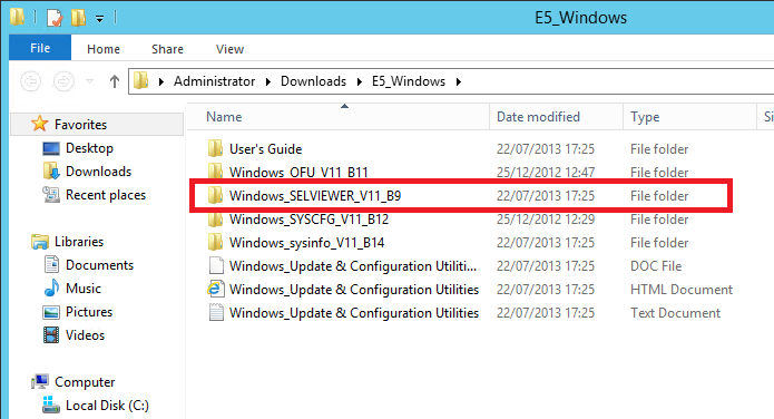
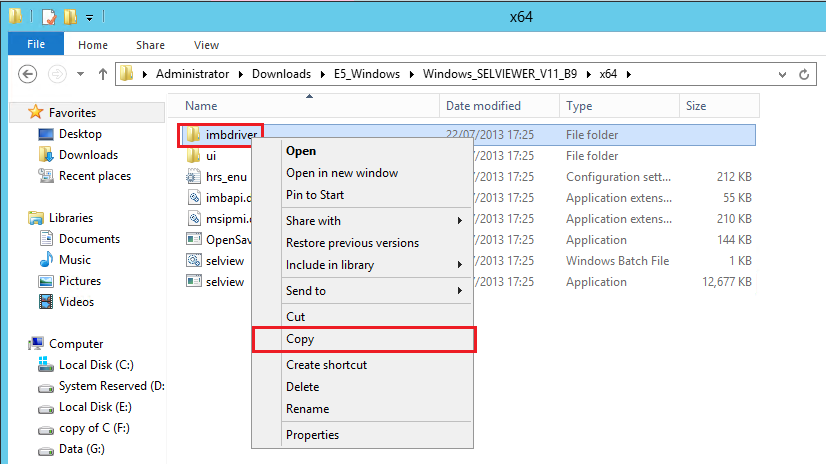
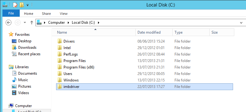
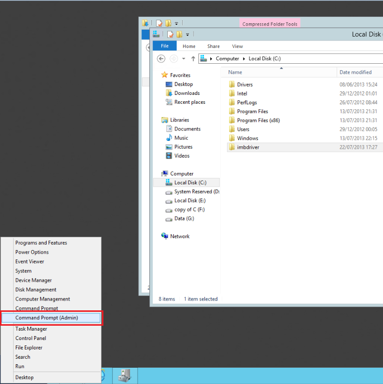
Detailed Instructions - Full Selview with User Interface1. Download the Windows Based SELVIEWER Tool for your platform. This package normally comes with several utilities bundled inside, including the Selviewer tool. 2. Extract the downloaded file into a subfolder. Sample below. 3. If you are running a 64-bit system (most likely) go into the x64 subdirectory. If you are running a 32-bit system, go into the x86 subdirectory. This is important as the edition of the IPMI driver must match your operating system (32-bit or 64-bit). 4. Then copy the IMBDriver subdirectory by right hand clicking on it, then left hand click on Copy 5. Paste the copied folder to the root of the C drive, i.e. C:\ 6. Open an Administrative Command prompt The quickest way to do this on Server 2012 is to move the mouse cursor to the far bottom left of the screen, and then the Start image comes up, right hand click on it. Then choose Command Prompt (Admin).
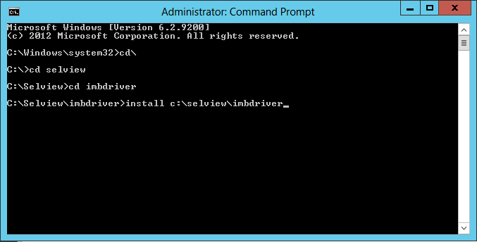
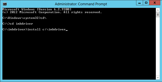
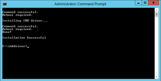
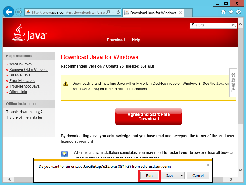
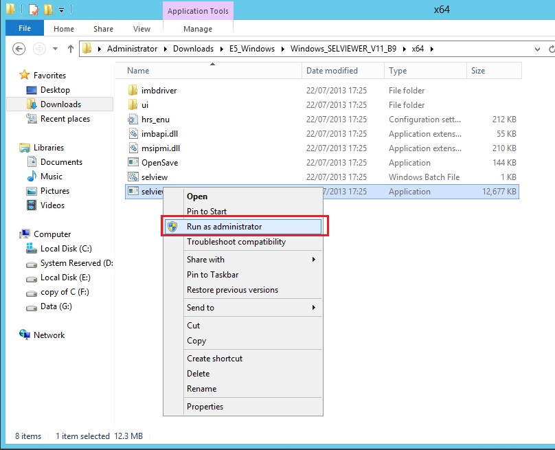
7. Inside the command prompt, change to the folder containing the IPMI driver, by using the CD command. For example: CD \ CD \IMBDRIVER 8. Then run the device driver installer: INSTALL C:\IMBDRIVER 9.This should then report that the installation was successful. Note that in most instances a reboot is not actually required. 10. Go back to the files you extracted earlier. 11. If your version of Selview requires Java, this will need to be installed first. You can double check if Java is required by checking for the presence of .JAR files in the UI subfolder. 12. If required, Install Java. If not required, skip to step 13. You will get either 32-bit or 64-bit Java depending on whether or not you are using a 32-bit or 64-bit browser to browse the internet. (64-bit browsers will require a 64-bit operating system). It is important to note or realise which version of Java is being installed as you will need to use the matching Selviewer program. (While the IPMI driver needs to match your operating system, the Selviewer program needs to match the Java edition you have installed). 13. Now run the Selviewer application. If your Selviewer doesnt require Java, then choose the version from the x86 or x64 folder which matches your operating system. Right hand click on the Application and choose Run as Administrator.
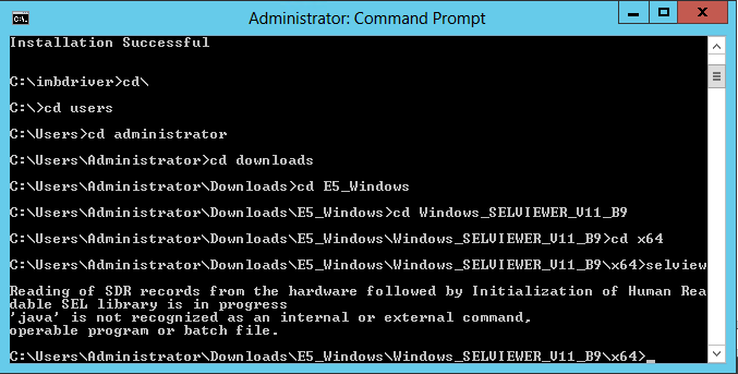
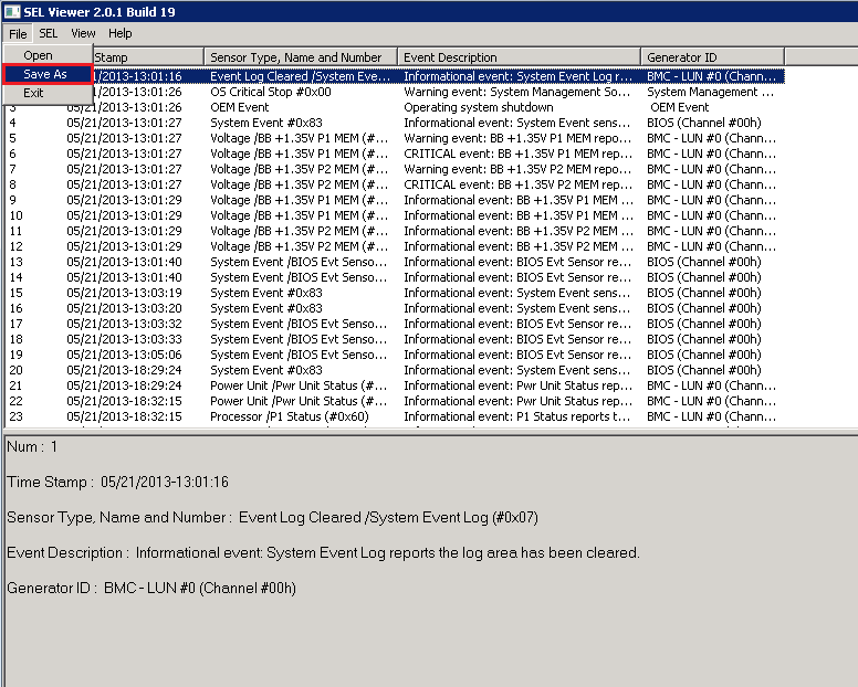
14. If the Selviewer interface doesnt run, try running the batch file by using the Administrative command prompt; change to the location containing the files and run Selview. You should get an error message indicating the problem. For example, in the screenshot below, Java is not installed: 15. When the Selviewer interface has loaded, use the File and then Save As option to save the events to a file.
16. Send the event log file to Stone for analysis. You can also use Wordpad or Notepad to examine the file. If the Selviewer program crashes when you run it, follow the instructions in the troubleshooting secion. Reminder: If you install the Windows 64-bit version on a 64-bit capable system but the SEL viewer fails to run, it may be because you either dont have any Java installed, or you only have 32-bit Java installed. It is possible to install the 64-bit IPMI driver and then use the 32-bit SELVIEWER utility with 32-bit Java installed.
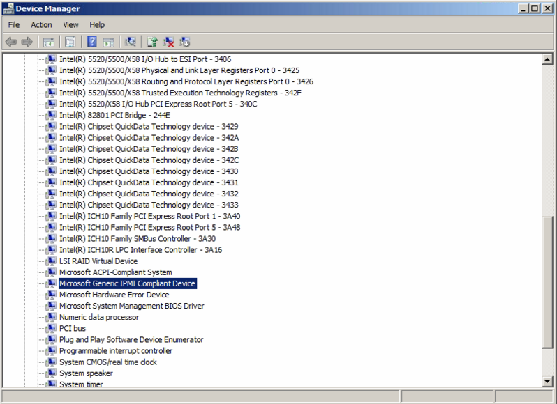
Troubleshooting - The Selviewer Program Crashes or Stops RespondingIf the Selviewer program crashes or stops responding when you run it, the problem is likely to be around the IPMI driver. Check Device Manager for the presence of a Microsoft IPMI driver or an older Intel IPMI driver. If it exists, you will need to use Device Manager to manually upgrade the driver to the Intel version contained in the SELVIEWER package. Re-running the "install" program for the IPMI driver will not solve the problem as this may not over-write an existing Microsoft IPMI driver. Applies to:
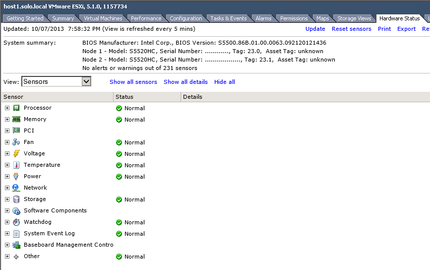
The Hardware Event LogMost modern servers retain hardware events, including informational, warning, and error events, in a dedicated hardware event logging system held on the motherboard. These logs can be useful in troubleshooting problems, such as a flashing hardware health symbol. With Intel based servers from the 2010 model year and newer, it is possible to retrieve these logs using the following methods:
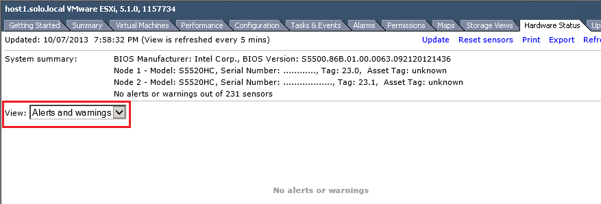
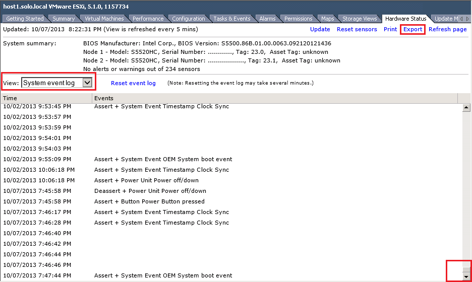
It is also possible to retrieve a basic hardware event log directly using the VSphere client for servers running the VMWare ESXi Hypervisor. The method to achieve this is below. InstructionsSteps:
Note: Events saved using this method may not be as detailed as obtaining the full SEL using the EFI tool, but it does allow the gathering of diagnostic data without interruption of service. If you are troubleshooting an issue and the guests have already been migrated to other hosts, we recommend you use the opportunity to gather a full hardware SEL log from the EFI (depending upon the model of server).
Applies to:
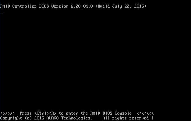
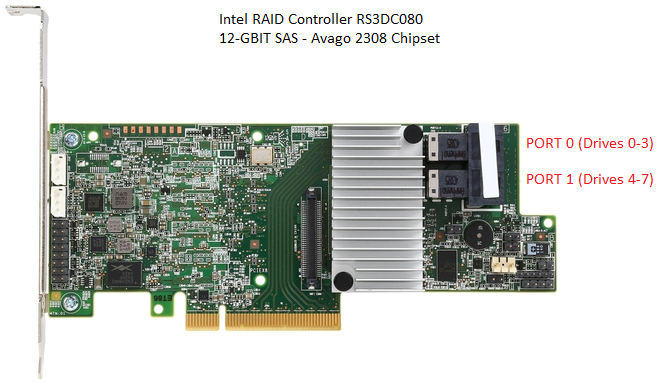
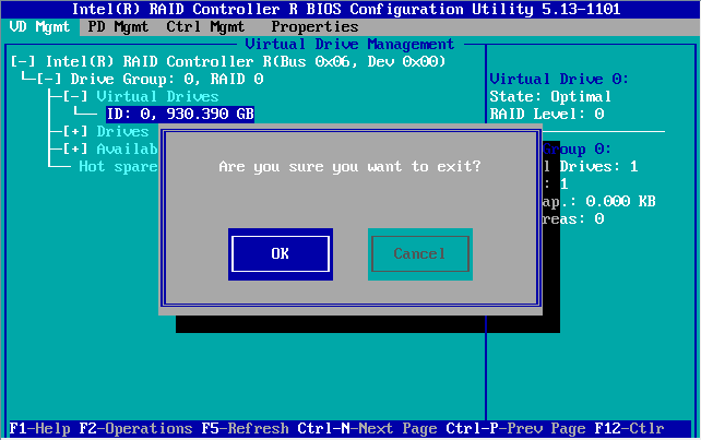
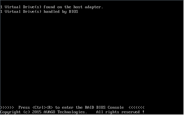
IntroductionThe new 12-Gbit SAS Hardware RAID Controllers use the new LSI / AVAGO 12Gbit SAS Controller Chipset, the 2308. Cards based on this chipset feature an updated RAID BIOS that reverts to a more text-based layout. The main functionality of the previous RAID Web BIOS is still available, but accessing it is different. Hint: Cards and modules which use the new chipset require you to press CTRL + R during the system POST process, instead of CTRL + G.
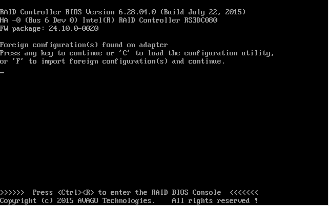
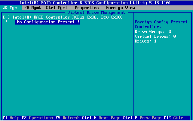
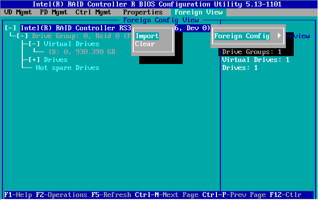
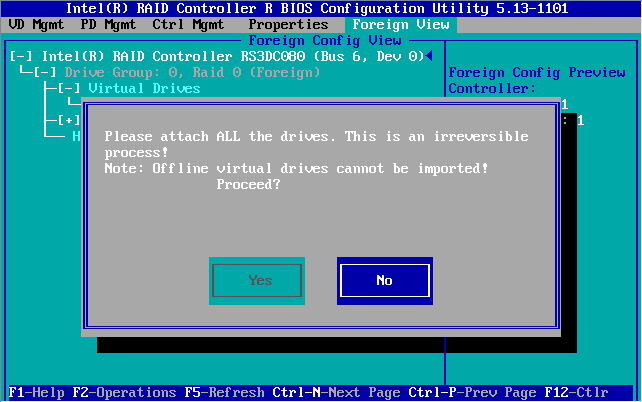
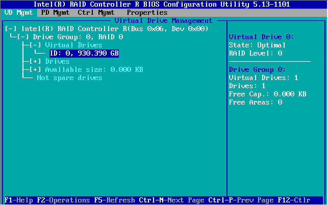
When Do You Need to Import a Foreign Configuration?A "foreign configuration" situation occurs when the configuration on the RAID controller doesn't match the configuration on the drives. This often happens if the RAID controller has just been replaced, or if the physical drives have been moved from one server to another. Many controllers with up to date firmware may automatically import foreign drives if there wasn't a configuration previously on the card. If this automatic import doesn't happen, or if your controller has been previously used, you will need to follow the instructions below. Before you start: If you have just replaced the RAID controller, always upgrade the RAID firmware before connecting the drives and attempting to import the RAID configuration. To upgrade the firmware, you will need the firmware files from the Intel web site and a FAT32 formatted USB pen drive. Upgrade the firmware using the EFI Shell.
Instructions:
Applies to:
ProblemThe wired network card in you some servers or workstations which include the Intel i350 network adapter may connect to the network slowly: Symptoms include:
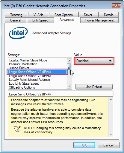
CauseThis appears to be a driver issue and has been found in driver version 18.3 through to version 20.1 (June 2015). Disabling advanced ethernet options such as support for Energy Efficient Ethernet (EEE) has no improvement. This issue has only been observed in Windows 7 but likely applies to Windows Server 2008R2. Work AroundDisable TCP/IP v4 Large Send Offload V2. To do this:
Applies to:
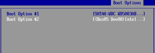
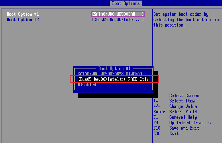
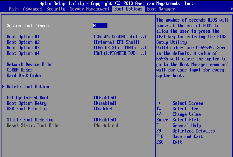
System Not Booting from a Hardware RAID CardIf your server is not booting from the RAID system - for example, the operating system does not appear and/or you get messages about the system trying to boot from the network, or possibly it the system boots into the EFI Shell - there are seven main possible reasons:
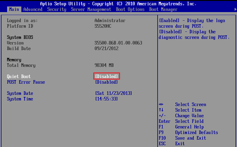
In all situations please note any error messages or other symptoms and contact Stone support for further assistance. Some Resolutions to the AboveThis will enable you to see all of the POST messages and see the RAID BIOS start.
Tip: If you can't get into the BIOS at all using F2 - if the system remains stuck on the splash screen - you may well have a RAID card error message "hidden" in the background. The RAID card may be waiting for certain key-presses. To get around this, turn off the system, remove the RAID card from the system (noting any cable connection order), turn off quiet boot as above, then shut the system off again and re-fit the RAID card.
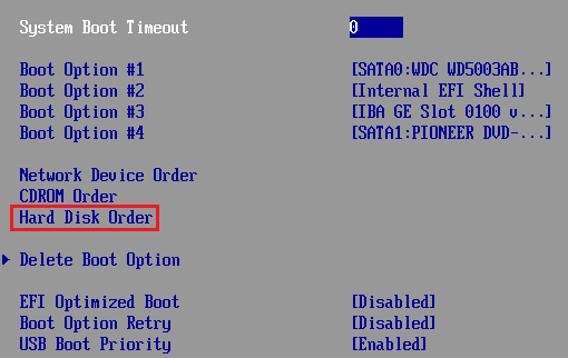
Use this process to check that the main BIOS is attempting to boot from the RAID card, or to check that the RAID card is being identified by the system. If the RAID card does not appear as a boot option, the card may have failed, its BIOS may not be enabled, or more likely its virtual drive has failed meaning that the RAID card has no bootable device to present to the main BIOS. The instructions below are based on an Intel S5520HC system but are applicable to most modern Intel based server systems.
If the RAID card is not in the list of options:
Configuring the RAID Boot Volume
Applies to:
ProblemEntry level server systems based on the S1200BTL (ATX) or S1200BTS (uATX) system boards can loose second LAN port functionality. The LAN port is not detected in the operating system; it is not available in device manager. Products
IssueThis issue should only occur if you have recently completed one of the following:
In these instances the second LAN controller can be disabled due to a BIOS problem. You will need to manually re-enable the second LAN controller. Root CauseThe root cause is a BIOS glitch that Intel have documented. Their resolution is described below. ResolutionEnsure both controllers are enabled in the BIOS:
Note: If both LAN controllers are enabled in the BIOS and still one controller is missing in the operating system, or if the LAN controller repeatedly disappears even though you have not met the circumstances in the Issue section, then please contact Stone for warranty service.
Applies to:
Problem
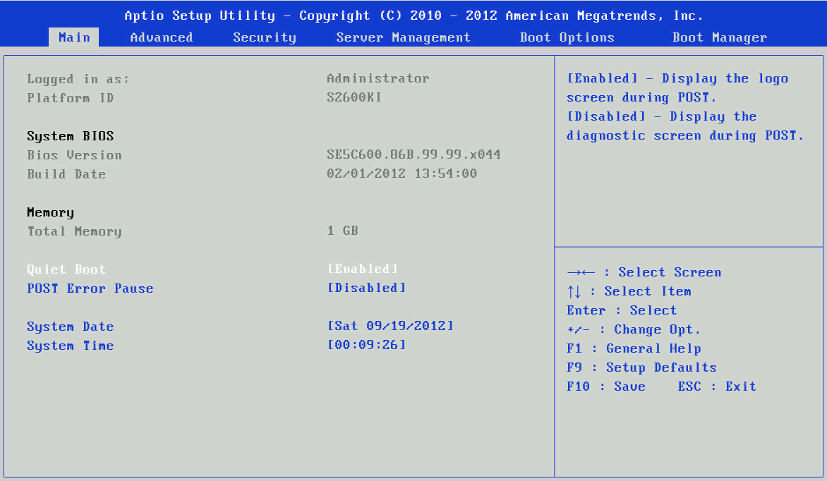
CauseThis is caused by the Intel Quiet boot setting on the server board BIOS. This causes the Intel splash screen to be displayed; all RAID and system error messages are hidden behind it. This means that any RAID card prompts (i.e. something that requires a key-press or some action) causes the system to appear to hang, as you never see the instructions. The system will not enter the BIOS until the RAID card BIOS completes. Scenario This can happen either after motherboard or RAID card replacement, or on a system that has been running fine but has experienced a RAID event (such as a failed volume, card fault or RAID battery issue) causing the RAID card to start to need corrective action during the boot process. ResolutionIn this situation you may find that waiting for the BIOS setup to appear may happen after a considerable wait - for example, after the RAID card times out - but often this is not the case. You need to disable Quiet boot in the BIOS but in order to gain access to the BIOS you will need to remove the RAID card from the system. Disable Quiet Boot This will enable you to see all of the POST messages and see the RAID BIOS start.
Remember: When performing a RAID card replacement, or motherboard replacement, always ensure that you disable quiet boot before fitting the RAID card. Also remember that any replacement RAID card may also benefit from a firmware update - this needs to be applied before the drive cables are connected and the foreign volumes imported.
Applies to:
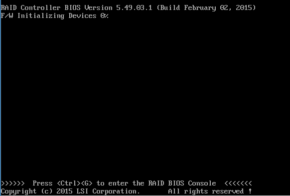
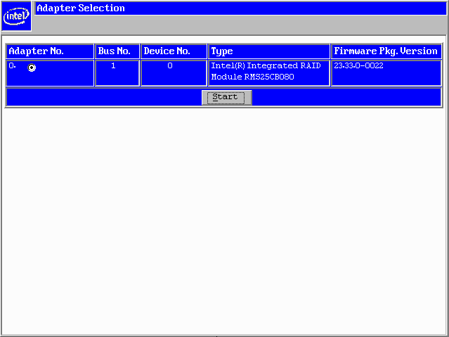
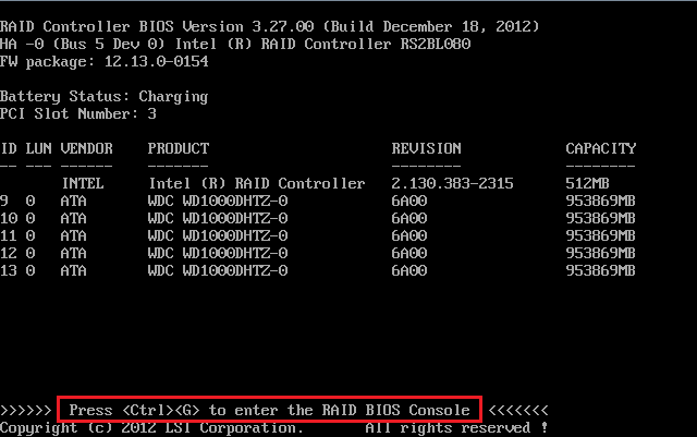
ProblemOn some combinations of hardware RAID card and server or workstation motherboard, when you attempt to go into the RAID Card BIOS Console the system ignores the request and boots normally. For example, you press CTRL+G during the RAID initialisation screen when an RMS25CB080 is fitted, but unexpectedly the RAID Card BIOS Console does not start when POST completes. CauseThis is normally caused by a compatibility issues between the RAID card or module and the motherboard. ResolutionBoth a resolution and workaround are available for this issue. For the workaround, scroll down. To resolve the problem, ensure that both the motherboard BIOS and RAID BIOS are up to date. Usually this can be done on most modern motherboards using the EFI environment, meaning that you don't need to access the RAID BIOS Console to actually perform the update. WorkaroundsTwo work arounds are available - Work Around 1 uses the Boot Menu (F6) and Work Around 2 uses the BIOS Setup (F2). Work Around 1 - Using the Boot Menu (F6) Do the following:
Work Around 2 - Using the BIOS Setup (F2) Do the following:
Applies to:
Overview of the RAID Card Replacement Process
Note: RAID Card firmware updates in the above process will almost certainly need to be done in the EFI environment. If you perform any updates using RAID Web Console from within Windows, do NOT use the option to enable the RAID firmware update to take immediate effect. The firmware update may be flashed whilst Windows is running, but the system should then be rebooted for it for take effect.
Overview of the Motherboard Replacement Process
Remember: When performing a RAID card replacement, or motherboard replacement, always ensure that you disable quiet boot before fitting the RAID card. Also remember that any replacement RAID card may also benefit from a firmware update - this needs to be applied before the drive cables are connected and the foreign volumes imported.
Applies to:
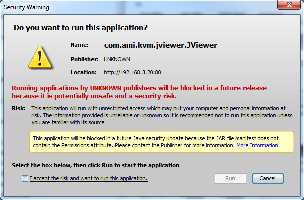
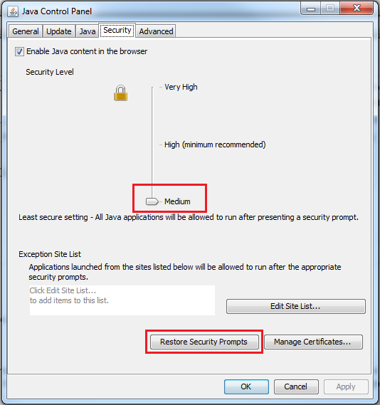
ProblemCustomers using the AXXRMM4 (RMM4) or AXXRMM3 (RMM3) remote management modules may experience a security message when they try and use the remote keyboard/video/mouse (KVM) feature. The security message may either completely block the page or warn that the application may be blocked in future, depending on the version of Java installed or the Java security settings in force.
CauseThis issue is caused by the Baseboard Management Controller (BMC) on the motherboard having KVM applet code which does not include the proper publisher identifier information. ResolutionWork Around 1
Work Around 2
Work Around 3
Resolution 1 (for W2600/S2600/S2400 series based systems only - Xeon E5)
Resolution 2 (for S5520HC and S5520SC only)
Applies to:
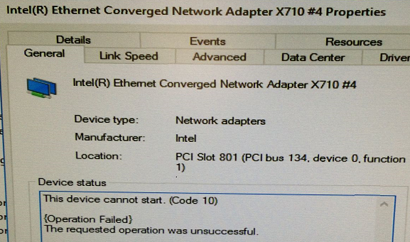
ProblemThe Intel X710 Series 10Gbe Dual or Quad port network adapters may report that one or more ports cannot start. The problem may appear if the driver was recently upgraded either through Windows Update, or by downloading the updated driver from the Intel web site. The network card instance in Device Manager is shown with an exclamation mark, indicating a problem. CauseThe problem is due to an issue with the non-volatile memory area on the adapter Resolution
nvmupdate64e -u -l -o update.xml -b -c nvmupdate.cfg
More Information
Applies to:
Why Use RAIDRAID systems can add resilience against disk failures and/or combine the performance of many disks into a fast single volume. It is important that any faults or error messages with RAID systems are promptly examined to ensure that data is protected. How to Monitor the RAIDYou should always keep installed the RAID monitoring software for your RAID adapter. This includes:
Hardware RAID is recommended for most server applications and this article deals with the management of an Intel Hardware RAID system. Dos and Don'ts
Remember: The protection that a RAID array gives against failure is NOT a replacement for having adequate backups. Always have proven tested backups for your operating system, system state, and most importantly, your data.
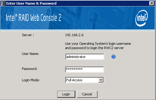
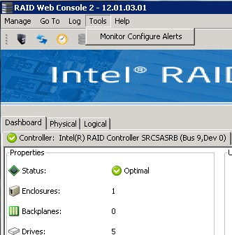
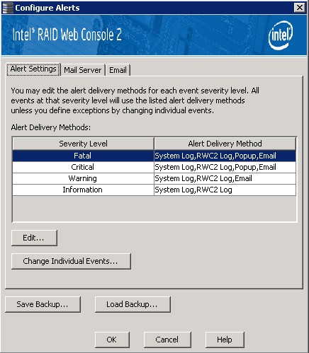
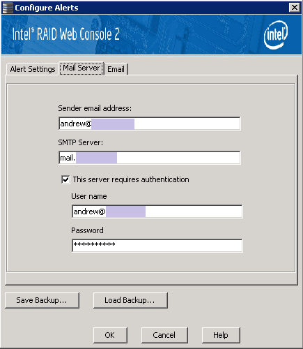
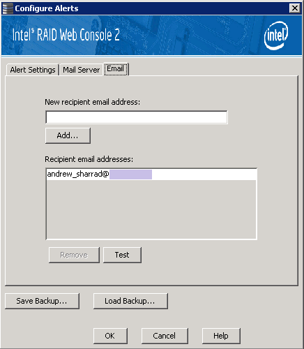
Planning your RAID SystemWhen planning and implementing your storage system, consider the performance, capacity and resilience that your system requires. For example, a VMWare virtual server in a SAN environment may be able to run the operating system using RAID1, as the operating system disks have little load most of the time (unless the system has more virtual RAM committed to guest operating systems than physical RAM available, in which case VMWare may page to disk and this will put a load on the local storage). Another example is a file server with a large RAID array. In this situation, consider using RAID6 and possibly include a hot-spare as well. MonitoringEspecially when the server is not in a location where you can hear audible failure messages, it is important to set up email alerting. Even if the server is is in a place where you would normally hear an alarm, the use of email alerts can help you be aware of problems when you are away from site. Use the MSM / RWC2 Email Notification FeatureSteps to Setup Monitoring
FinallyPlease review our other RAID articles as these cover topics such as troubleshooting, the RAID levels available, and the differences between desktop and enterprise class hard drives. Applies to:
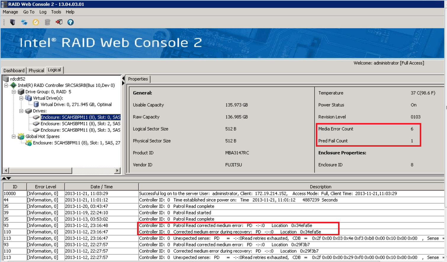
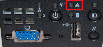
Diagnosing ProblemsIf your Intel hardware RAID system is beeping this almost always indicates a hardware fault. Faults need to be investigated and corrected promptly. The easiest way to do this is to always set up your servers or systems with the correct monitoring software when you install the system. This means that you do not need to find additional utilities or software when your system is in a potentially dangerous state. Contact SupportAlways contact Stone Support for warranty service and advice. We can help you when your system has a problem and help protect your data. The steps below are provided as a guide and are not exhaustive. They are based on a system with an Intel / Avago / Broadcom / LSI hardware RAID controller or module. If your System is Beeping
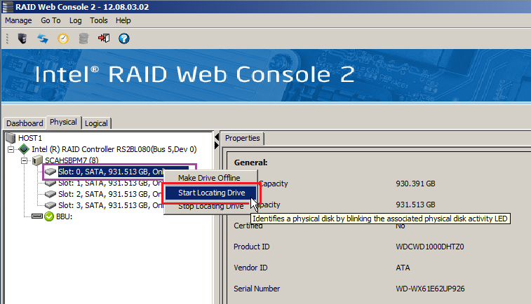
Remember: An Amber/Orange drive bay light may not necessarily indicate that that drive is faulty - it could be that the drive in that bay was previously available as a Hot-Spare and the system is rebuilding onto it. Check for the presence of other amber lights or other "Unconfigured Bad" drives in the RAID console.
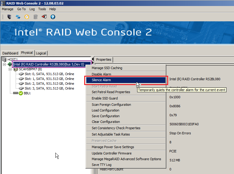
Silencing the AlarmIf the RAID system beep is distracting your users, the alarm may be temporarily silenced. To do this:
Important: Do not use the feature to Disable the Alarm, as this will prevent you from hearing the audible alarm if there are future failures, or for example the rebuild process fails to complete.
Replacing Hard DrivesYour Stone warranty service will carry out this for you, however some pointers are given below: Do:
Applies to:
Problem
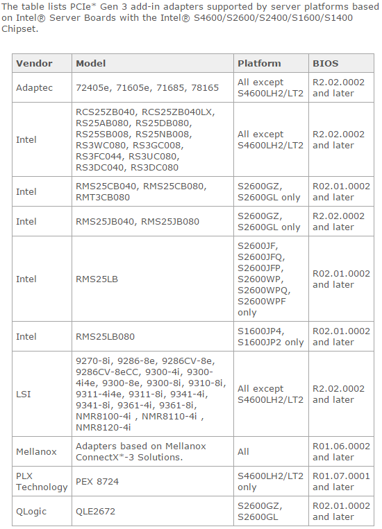
CauseThis can be caused on S1400 / S1600 / S2400 / S2600 Intel server or workstation boards by the use of an un-validated or unsupported PCI Express Gen.3 (generation 3) add-in card that has been fitted to a system that has a PCI Express Gen. 3 capable processor. More InformationIntel originally released most of the above server platforms for PCI Express Generation 2 operation, namely for the first 32nm Xeon 2400 or 2600 series chips. The new 22nm V2 versions of these chips support PCI Express Generation 3, which increases the data transfer rate. However, the system boards only support these increase data transfer rate on certain Intel validated add-in cards. The list of validated cards varies according to the Intel motherboard in use. ResolutionAdd-in cards which are not validated to run at PCI Express Gen. 3 on the affected server boards should have the appropriate PCI Express Slot configured for PCI Express Gen.2 operation only, by using the Processor PCIe Link Speed settings in the PCI Configuration menu. See the following for more information from Intel: Intel Summary of Supported Adapters as of March 2015Applies to:
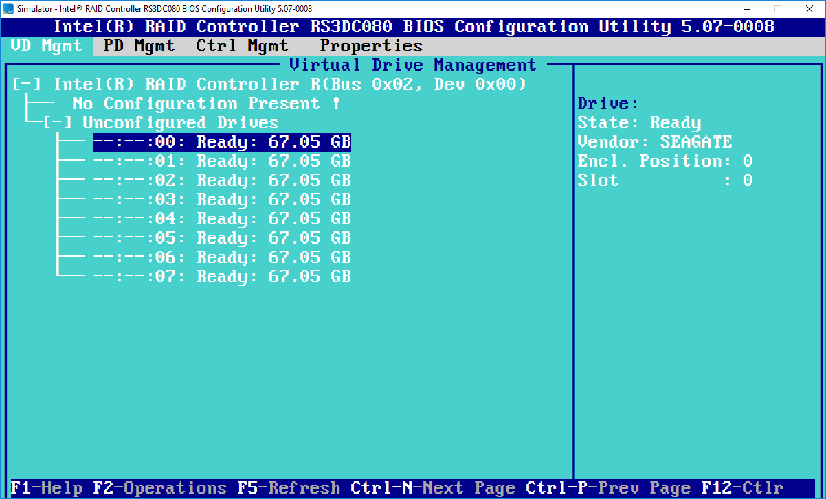
Please find below a link to the Intel RAID Simulator for 12G (12-Gbit) adapters on server systems. These controllers are available as either a plug in PCI Express Module, a PCI Express Card, or Integrated onto the motherboard. These controllers should not be confused with onboard software RAID or SCU controllers. This utility simulates the RAID BIOS interface a user would normally see when pressing <CTRL><R> during POST. It can be used for support or research purposes. Note: Use the Intel download link to obtain the latest version of this simulator.
Downloads
Applies to:
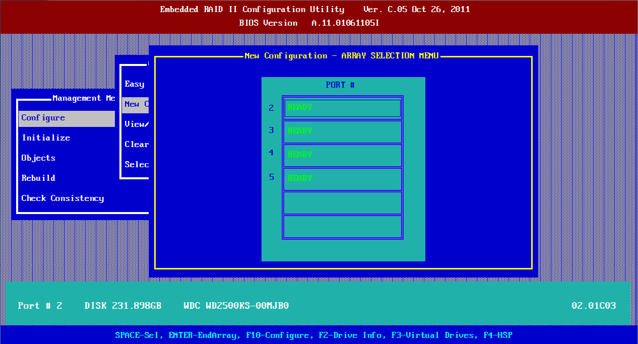
Please find below a link to the Intel ESRT-2 RAID BIOS simulator for server systems. This controller is integrated into a number of onboard SATA or SAS controllers to provide basic RAID functionality. Most implementations of this controller provide basic hardware or firmware assisted RAID. ESRT-2 RAID should not be confused with RST-e RAID. Intel Rapid Storage Technology - Enterprise - is a software based RAID solution with some additional logic and firmware build into the motherboard PCH chipset and BIOS in most cases. This utility simulates the RAID BIOS interface a user would normally see when pressing <CTRL><G> or <CTRL><E> (as dependant on model and BIOS message) during POST. It can be used for support or research purposes. Note: Use the Intel download link to obtain the latest version of this simulator.
Downloads
Applies to:
Please find below a link to the Intel RSTe RAID BIOS simulator for server systems. Intel Rapid Storage Technology - Enterprise - is a software based RAID solution with some additional logic and firmware build into the motherboard PCH chipset and BIOS in most cases. This utility simulates the RAID BIOS interface a user would normally see when pressing <CTRL><I> during POST. It can be used for support or research purposes. Note: Use the Intel download link to obtain the latest version of this simulator.
Downloads
Applies to:
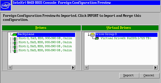
Recovering a Failed LSI or Intel RAID ArrayThis article will show you how to recover a failed RAID 5 array on an Intel or LSI hardware RAID controller. The same or similar process can also be used with other RAID arrays such as RAID 1 or RAID 6. It is important to understand first how drive configuration information is stored, and what a "foreign configuration" is, as you may see messages about this appear. What is a Foreign Configuration?Intel or LSI Hardware RAID controllers store RAID volume configuration information on both the drives and the controller. When the system is booted or a drive is inserted, the drives and configurations are examined and any configurations that don't match each other are flagged as a foreign configuration. The RAID controller will use its own configuration as the master record, to identify which configurations are invalid. All physical drives configuration information contains a list of the drives involved in the associated logical drive. What's the difference between Optimal, Degraded, Critical and Offline?RAID controllers use these terms to show the health of the logical drive.
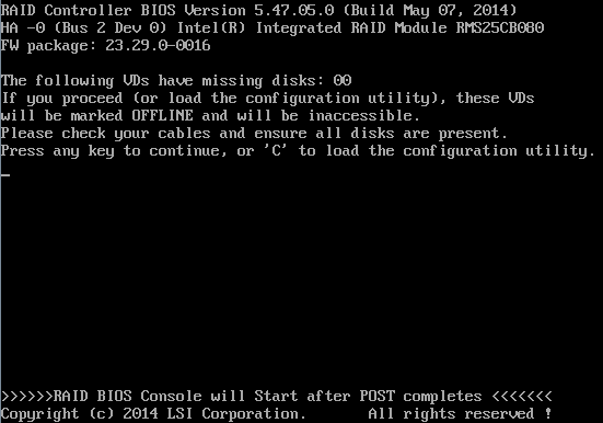
For example, RAID6 arrays can lose up to two drives. The loss of one drive will result in the logical drive being reported as degraded, not critical. Scenario 1 - The system is booted but not all of the drives are plugged in, possibly due to a loose cable. Messages such as the one above require prompt action:
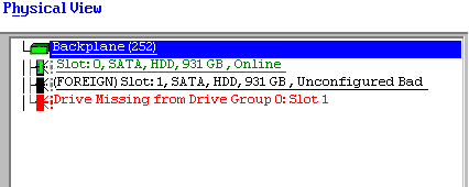
Scenario 2 - A drive has failed, but now a message about a Foreign Configuration has appeared Hard drives which encounter problems such as bad blocks or a controller fault may stop being able to be detected. The drive may then become "available" again, perhaps after the drive has reallocated the bad blocks. However, when the drive failed, the RAID card will have written a configuration update to itself and the remaining drives, notifying the failed drive. The configuration on the failed drive is now out of date and does not match the other drives, so it is flagged as having a foreign configuration.
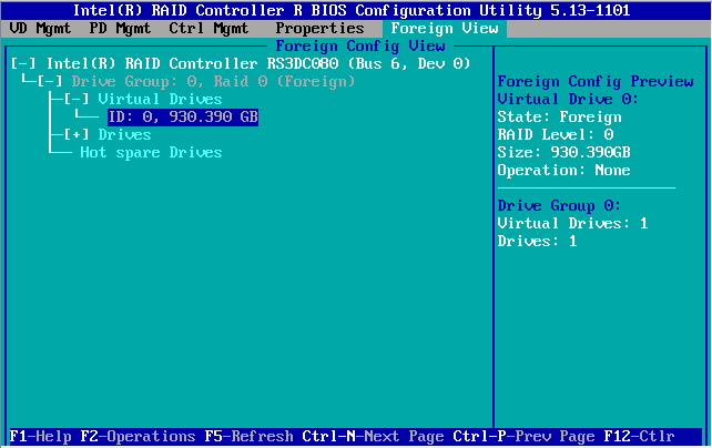
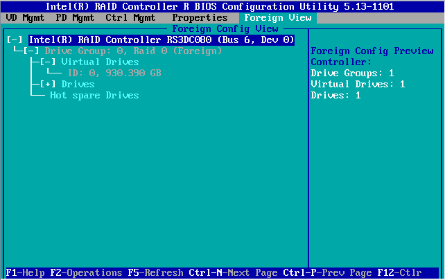
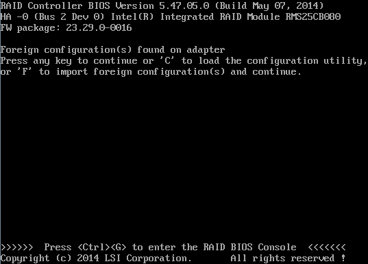
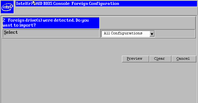
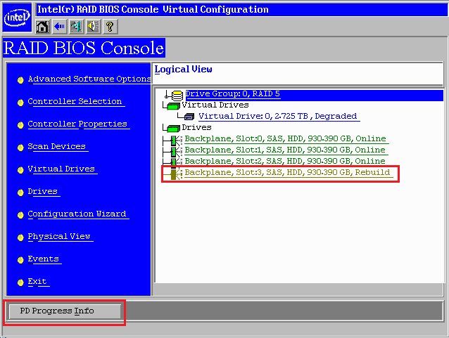
Scenario 3 covers importing a foreign configuration. Scenario 3 - The drive was disconnected accidentally, my array is offline and I need to recover it. Disconnected drives will either be marked as Foreign, or Unconfigured Bad. Unconfigured bad drives cannot be have the foreign configuration imported until you mark the drive as "Unconfigured good". Foreign drives detected on the RAID card boot may be flagged as below. In this instance, either Press F, or better still, press CTRL+G to enter the RAID BIOS and manage the foreign configuration process. Some older RAID cards may allow you to Import a foreign configuration without Previewing it. However we recommend you always preview the configuration to be imported and check that all logical drives - including those that have no problem - are correctly shown. If you have different drives with different foreign configurations then you may have multiple choices to try and import. Try "All Configurations" first. If this does not work, try each configuration in turn, making sure you preview it first. It is likely that only the configuration from the last drive that failed will be importable. Tip: If you can still boot your operating system such as Windows - for example, you are managing a problem with your data logical drive, but your operating system logical drive is still functioning, you may find it easier to boot Windows and use the Intel RAID Web Console to manage the array recovery. Right hand click on the RAID controller from inside RAID Web Console and select "Scan Foreign Configuration" to start the import process.
Scenario 4 - I'm Running RAID 5 and my system crashed. I appear to have had two hard drives fail. This can happen especially if you have a hot-spare drive. When the first drive fails, the RAID card will start rebuilding onto the spare. The unusual workload may cause another weak drive to then experience a failure. Tip: Using RAID 6 instead of a RAID 5 plus hot-spare configuration prevents you from being in this situation. RAID 6 will still require a logical drive rebuild but RAID 6 can withstand up to two drive failures without going offline.
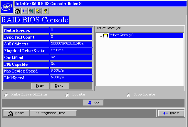
In this scenario you may not may not get messages about a foreign configuration. If you do not, or if the foreign configuration does not import, follow the steps below:
Note: In some situations when you have multiple drive problems you will not be able to go into the RAID BIOS when there is a foreign configuration present, even if it will not import. Do not clear the foreign configuration, as you should always attempt the least destructive operations first. In this situation, determine which are the problem drives by the orange LEDs on the front of the server. Turn off the server, and then remove one drive. Boot the server backup and attempt the import process, or mark the drive as Unconfigured good and then reboot, and attempt the import process again. Only the last drive to have failed will likely import, but it does mean that this last drive needs to be healthy enough to get the RAID array back to a degraded or non-critical state.
In All Situations
What Can I do to Minimise the Chances of Unexpected Failures?
Applies to:
ProblemOn some Intel servers a glitch with the RAID Copyback feature can cause the RAID Card to continue to beep even after a failed drive has been replaced. The system may start beeping again when the system is rebooted. BackgroundThe Intel RS2BL040 and RS2BL080 are 4 and 8 port controllers based on the LSI 2108 first generation 6G SAS chipset, and are Intel's branded version of the LSI 9260-4i and 9260-8i respectively. These cards have shipped in large numbers of Stone servers since 2012 to 2016. There is a wide variety of firmware versions in use in the field. During the card's life, new features have been added by Intel including the Copyback feature. Problems with the Copyback FeatureThe Copyback feature is designed to rebuild back onto the original drive slot after a RAID repair to a hot-spare has been completed. For example: Pre-Failure state:
State after drive failure:
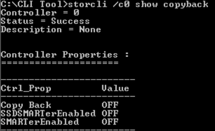
With Copyback, the idea is that when you replace the failed drive in Slot 1, that the system rebuilds onto Slot 1, and Slot 2 reverts to being the hot-spare drive. In some versions of Copyback, notably with firmware version 0104, when you replace a failed drive in a system that does not have a hot-spare, the act of marking a new drive as a hot-spare to begin the rebuild process leaves the system requesting a second rebuild after, to complete Copyback. RecommendationTo avoid a copyback issue on the RS2BL040 or RS2BL080 with firmware version 0104, either change the RAID card properties so that it automatically rebuilds, disable Copyback, or upgrade the Controller firmware before replacing the drive. To Set Automatic Rebuilds On You will need the Command line utility Storcli. This can be used inside EFI or a Windows environment. Use the commands below to list the controllers and get the right controller number, i.e. 0 or 1. For example, you may have an onboard ESRT2 controller - usually controller 0 - and an add-in RAID module or controller, usually controller 1. storcli show To show the existing auto-rebuilld setting: storcli /c0 show autorebuild To enable auto rebuild on controller 0: storcli /c0 set autorebuild=on To Disable Copyback Again, you will need the Command line utility Storcli. This can be used inside EFI or a Windows environment. To disable Copyback on controller 0: storcli /c0 set copyback=off type=all Tip: On this model of RAID card it is not possible to set the Autorebuild or Copyback features from the RAID BIOS. It is also not possible to set this using RAID Web Console.
To Check That Copyback is Disabled Run the command below: storcli /c0 show copyback To Upgrade the Firmware See the attached article. What If I Have Already Replaced the Drive and my System Beeps?First, download the RAID TTY log using RAID Web Console to confirm the cause of your issue. If Copyback is the cause you of your problem, you will need to either:
More Information See this Intel article. Applies to:
BackgroundThe Intel RS2BL040 and RS2BL080 are 4 and 8 port controllers based on the LSI 2108 first generation 6G SAS chipset, and are Intel's branded version of the LSI 9260-4i and 9260-8i respectively. These cards have shipped in large numbers of Stone servers since 2012 to 2016. Therefore, it is useful to know how to replace failed cards and upgrade the controller firmware. The RS2BL080 is also a suitable replacement for the older SRCSASRB and SRCSATAWB controllers. This article gives some more hints and tips specific to the RSB2L0x0 cards in addition to the Overview of the RAID Card Replacement Process. Click on one of the links below for further instructions.
I'm Upgrading to the RS2BL040 or RS2BL040 from an older RAID cardIf you are upgrading from an older card, you need to follow the process below:
I'm Replacing the same card like for likeFollow the process below:
Reminder: RAID Card firmware updates in the above process should in the EFI environment, as the firmware on the card should be upgraded before you can connect the drives, thus before you can boot Windows, in most situations. If you perform any updates using RAID Web Console from within Windows, do NOT use the option to perform an "online update". This feature enables the RAID firmware update to take immediate effect and is not recommended. The firmware update may be flashed whilst Windows is running, but the system should then be rebooted for it for take effect.
Firmware Flash Methods and Examples
Applies to:
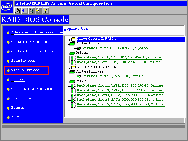
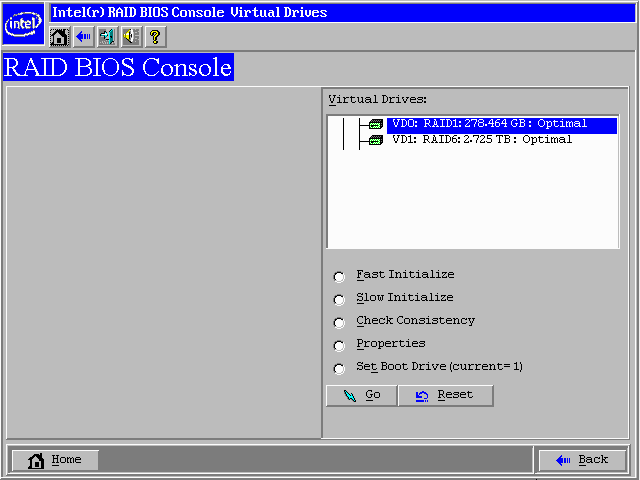
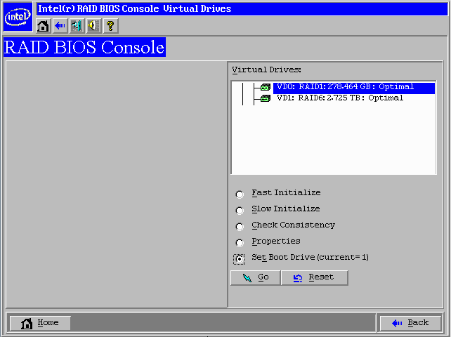
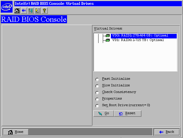
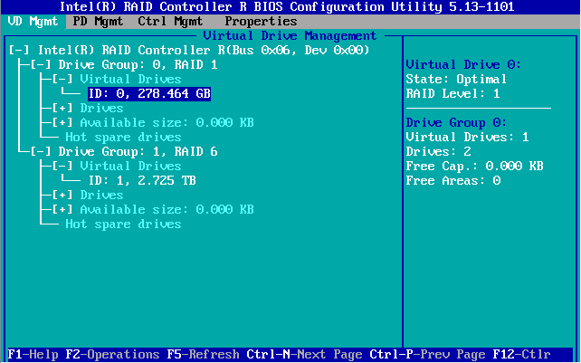
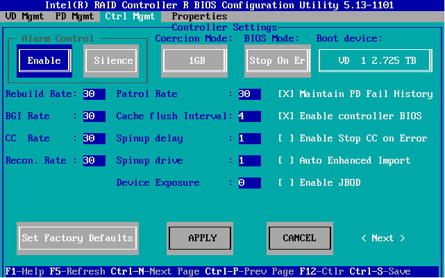
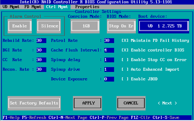
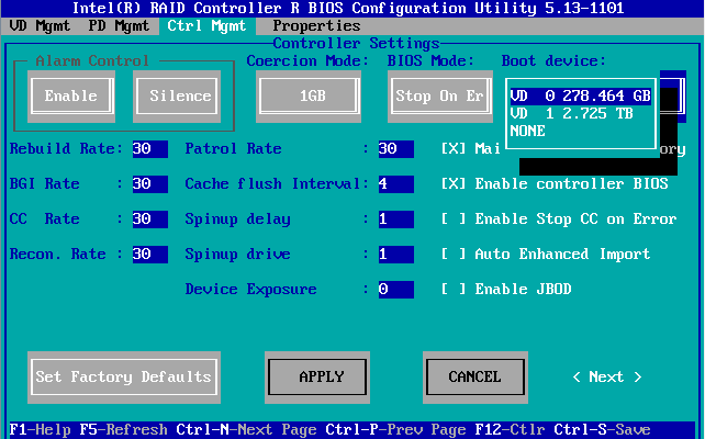
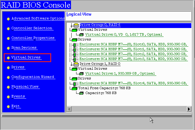
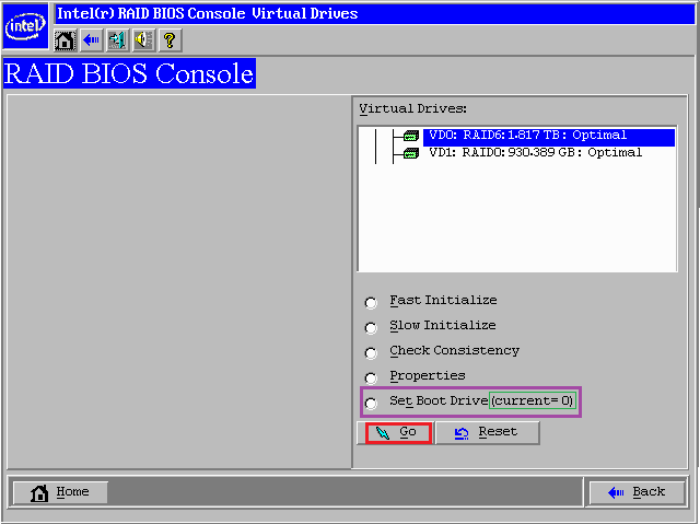
Setting the Boot Virtual Drive (VD)Hardware RAID cards support multiple virtual drives. For example, you may have a RAID 1 volume for the operating system, and a RAID 6 volume for your data. These will likely be identified as virtual drives VD0 and VD1. In a similar way that the main motherboard BIOS can be set to boot from different devices - including the RAID controller - the RAID controller itself can be set to boot from different virtual drives. If you have moved or recovered a virtual drive, you may need to configure the controller to boot from the correct drive. An indication that this is require is if the RAID card is seemingly ignored in the boot order, or if you get a BIOS message about an invalid boot device, or an invalid boot loader. The instructions vary depending on whether or not you have a 3G or 6G controller, or one of the new 12G controllers.
Instructions for 3G / 6G Controllers (Graphical-mode RAID BIOS)
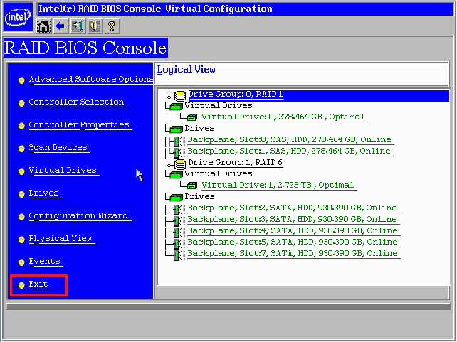
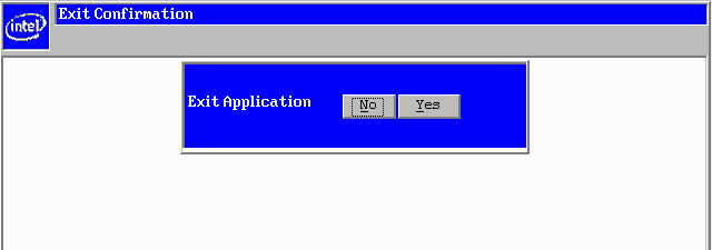
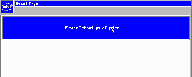
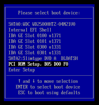
Instructions for 12G Controllers (Text-mode RAID BIOS)
Tip: When you have made any RAID BIOS changes, if your system still does not boot the operating system please re-check the made system BIOS device boot order.
Applies to:
IntroductionThe SysInfo tool (System Information Retrieve Utility) is a utility available for most S2400 and S2600 systems. It records the hardware SEL Log but additionally lots of other useful diagnostic information. When trying to debug an issue, it is usually easiest to retrieve the basic SEL log. If this does not reveal the cause of the problem - and you definitely have a hardware problem, for example the system warning does not show a solid green indication - then you may need to use the Sysinfo tool to gather additional information. Download the SysInfo tool from the motherboard or Server systems download page. For example: S2600 Family - Tool is available here. M50CYP Family - Sysinfo tool is available here. SysInfo Tool InstructionsWindows
UEFI
Note: The Sysinfo tool may take several minutes to generate the diagnostic files.
System Event Log Troubleshooting GuideIntel have made available a guide to help interpret Selviewer and Sysinfo information. The guide is available here, or attached. This guide allows you to decode the hexadecimal information of events recorded in the Sysinfo log to determine, for example, a problem sensor or reading. Applies to:
Limited SEL Log Storage SpaceThe hardware event logs retained by the motherboard's Baseboard Management Controller (BMC) are stored in a limited capacity flash memory. When this memory has been filled, you will usually find that SEL events are not stored. For example, if you save a SEL log and find that is has a few thousand entries, but the newest entry was some time ago, then it is likely that the SEL log is full. How To Clear the SEL LogClearing the SEL log in the motherboard's memory will allow new events to be stored. To clear the SEL log, use the SELVIEW utility, either from the Windows Command line or Internal EFI Shell - (or, for the older S5000 based server boards, use the SELVIEW utility from DOS instead of EFI). Simply type in SELVIEW /clear and then follow the confirmation instructions to clear the log. Applies to:
Problem
CauseIn a modern workstation or server system, the PCI Express Slots are almost without exception connected to the PCI Express Lanes on the system processors. This enables fast transfers and low latencies. Most Xeon E5-2400 or Xeon E5-2600 systems support up to two CPU sockets. Many (but not all) of these systems split the PCI Express slots in the system between the two processors. This means that if you have a dual CPU socket system, but only one processor is fitted, then some PCI Express Slots may be unavailable. Resolution
Tip: On most Intel Server boards, slots are numbered starting at 1, furthest from the system memory. This means that the PCH slot is usually Slot Number 1, although this varies from model to model.
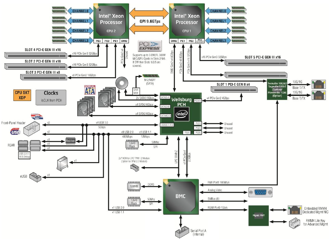
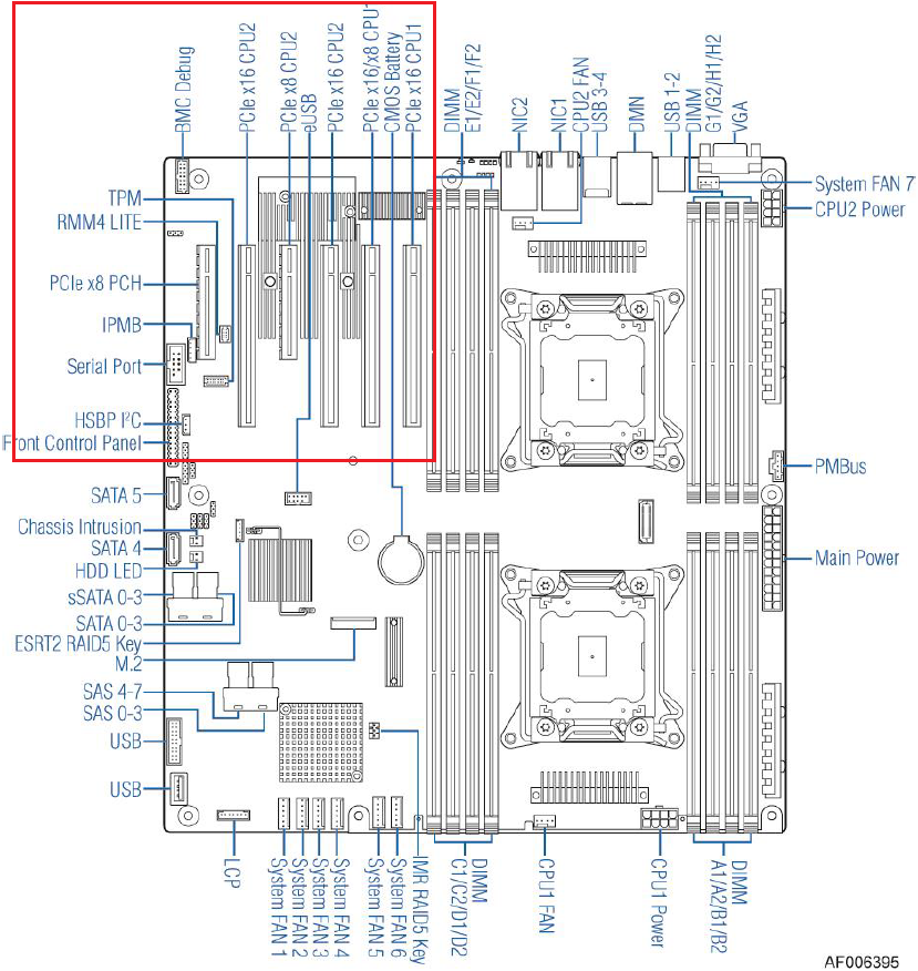
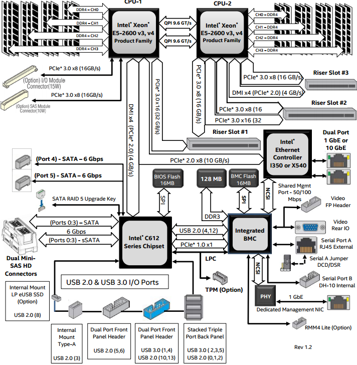
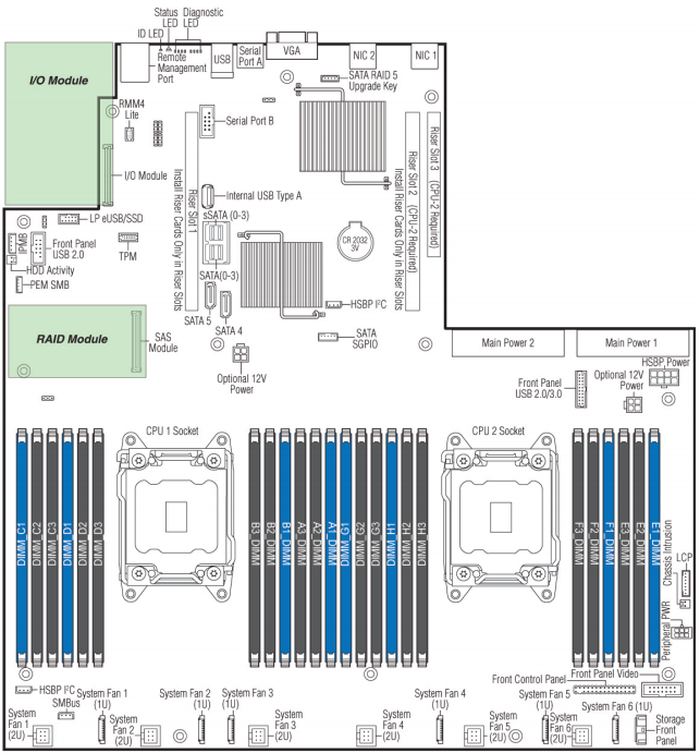
More InformationSample Layout Diagram 1 - Intel S2600CWThe first diagram shows the Slot availability as part of the chipset and processor layout; the second diagram shows the availability by physical slot.
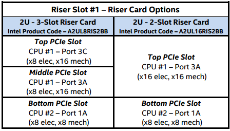
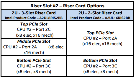
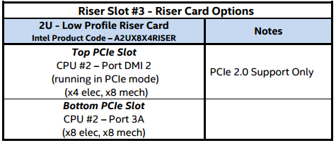
Sample Layout Diagram 2 - Intel S2600WT in an Intel R2308WTTYS chassisThe first diagram shows the Slot availability as part of the chipset and processor layout; the second diagram shows the availability by physical riser slot. The three riser diagrams from the System's Technical Product Specification show the PCI Express availability at each slot, and which processor provides the connectivity.
TerminologyPCH Slots PCI Express Slots connected to the PCH are usually x4 or x8 PCI Express slots connected to the motherboard chipset. Because they don't have a direct connection to the processor, the performance of these slots is often slightly lower. However they will always be available for use in whichever processor configuration. MUX Slots MUX Slots are PCI Express Slots that share some or all of the PCI Express lanes with other slots or devices. For example, a PCI Express x8 MUX based slot might have four lanes coming directly from the processor, and four more lanes that go via a MUX. The MUX shares the PCI Express Lanes between that slot and another slot. MUX based slots usually do not have any compatibility issues but bear in mind that the bandwidth on MUXPCI Express lanes is shared. DMI Slots PCI-DMI Slots are PCI Express Lanes running from a CPU. However, these lanes are normally used for CPU to Chipset communications. When implemented as PCI Express Lanes, the result is often a PCI Express slot that is slower or smaller, for example Gen.2 and x4. The Difference between Physical or Mechanical, And Electrical Some PCI Express Slots may not be fully wired. For example, a PCI Express x16 connector may, on some systems, only be x8 electrically wired. This means that half of the PCI Express lanes are unavailable. Plugging in a PCI Express x16 device may work if the device supports running with only half of the lanes connected, but it will run at reduced bandwidth. PCI Express Generations There are different generations of PCI Express available. PCI Express Generation 3 (or Gen.3) supports 8 Giga-tranfers per second, resulting in a little less than 1GByte a second of transfer performance per lane. If you have a PCI Express Generation 3 device, always use PCI Express Generation 3 slots in preference to PCI Generation 2 slots wherever possible. Applies to:
|








.png)



.PNG)
