Article Purpose
The aim of this article is to assist users that need to install Windows Server. It covers some of the common issues that are faced and shows you how to deploy Windows or Windows Server even on the most difficult of systems.
Topics
Downloading Mass Storage Drivers
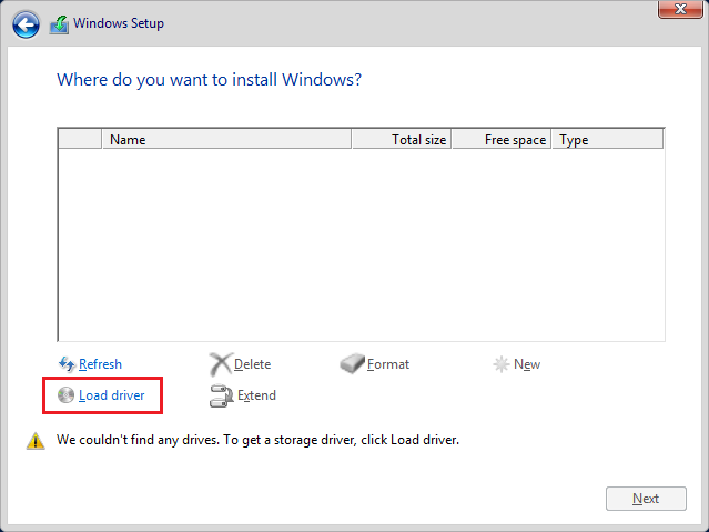
When installing Windows Server it is recommended to have the latest drivers for your RAID card, RAID module or integrated controller. If Windows does not find a hard disk to install to during setup, you will need to use the Load Driver option supply the drivers.
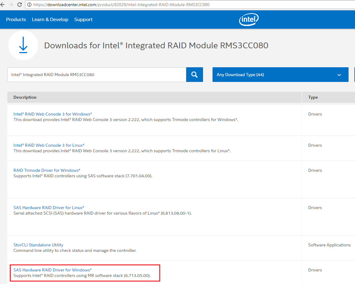
The drivers are available from the Stone Driver Finder (depending on model) or from the original component manufacturer's web site, such as Intel.
Note that your system may include a motherboard with several integrated controller (and driver) options. Some systems also include an add-in RAID controller or module for which more updated drivers or software will be available on a different page to the motherboard.
If you aren't sure what is included in your Stone system, or what you need, please contact Stone support for help.
Tip: If you download drivers in a ZIP file, make sure you extract the ZIP file to the pen drive, for use with Windows Setup. Windows Setup won't look inside ZIP files for drivers. It's also worth knowing that some component manufacturers don't supply Windows Server specific drivers. Instead, they provide drivers for the equivalent desktop operating system that shares the same platform underneath. For example, Server 2016 might need to use Windows 10 x64 drivers, and Server 2012R2 might need to use Windows 8.1 x64 drivers, depending on how the component manufacturer packages them.
Plan the Right BIOS Boot Mode for your System i.e. EFI / Legacy
Legacy mode is (as of 2017) still the default BIOS mode for many new servers. However there are more and more situations where UEFI mode (also known as plain EFI) mode is required:
- If you plan to use a TPM 2.0 module, for example as part of a Bitlocker deployment.
- If your organisation stipulates that Secure Boot must be enabled as part of a corporate policy. (Note that not all Server BIOS support Secure Boot).
- If your boot volume is greater than 2TB in size.
All three of these situations require UEFI mode. It's worth pointing out that you can install Windows in Legacy mode on a volume greater than 2TB. However, you can only use the first 2TB of the disk. This means that, for example on a 3TB disk, 1TB will go wasted. These limits are caused by historical limits to Master Boot Record (MBR) partitioning, which has a 2TB limit. GUID Partition Table (GPT) partitioning does not have this limit, but GPT volumes can only be booted using UEFI BIOS.
You can install Windows onto a separate, smaller volume in Legacy BIOS mode, and then access the entire 3TB volume as a secondary volume. This is possible because Windows can still create a secondary volume using GPT, and access more than 2TB, but it just won't be able to boot from it.
The following are not reasons for UEFI booting your server:
- Deploying virtual TPM, or vTPM services to guest operating systems
- If your boot volume is less than 2TB in size (secondary data volumes that are not used for booting can be any size, including over 2TB).
BIOS Boot Facilities
| BIOS Mode |
Supports GPT Partitioning |
Supports MBR Partitioning |
Supports Secure Boot |
Boot USB:FAT32 |
Boot from USB:NTFS |
| Legacy |
No |
Yes |
No |
Yes |
BIOS Dependant; Rufus provides bootloader |
| UEFI |
Yes |
Yes |
BIOS Dependant |
Yes |
BIOS Functionality
| BIOS Mode |
Support x64 |
Supports TPM 1.2 |
Supports TPM 2.0 |
Supports Server 2016 |
| Legacy |
Yes |
Yes |
No |
Yes |
| UEFI |
Yes |
Yes |
Yes |
Yes |
BIOS Disk Limits
| BIOS Mode |
Can Boot from Disk > 2TB |
Second disk can be > 2TB |
| Legacy |
Yes, but only first 2TB accessible due to MBR limits |
Yes, as second disk can be GPT but not booted from |
| UEFI |
Yes, as UEFI can boot GPT disks. |
Yes |
Note: Read below for other BIOS settings, and on setting up your RAID volume, before making your final BIOS UEFI/Legacy mode selection.
Changing the BIOS Mode
Intel E3 Platforms such as S1200V3RPL
- Go into the BIOS using the F2 key as the system starts
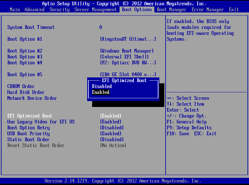
- Go to the Boot Options Screen
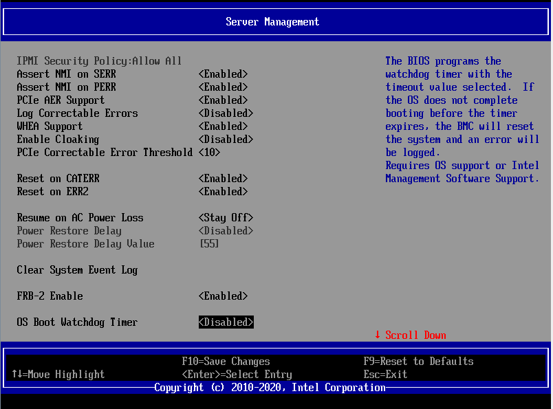
- For EFI Mode:
- Under EFI Optimized Boot, set this to Enabled
- Under Use Legacy Video for EFI OS, set this to Enabled
- For Legacy Mode:
- Under EFI Optimized Boot, set this to Disabled
Note: EFI optimised boot Enabled only supports booting EFI / UEFI devices. However, disabling EFI optimised boot allows the booting of both EFI and Legacy devices. If you want to be sure which mode your Server is booting in for the installation of Windows, prepare your USB installation media accordingly.
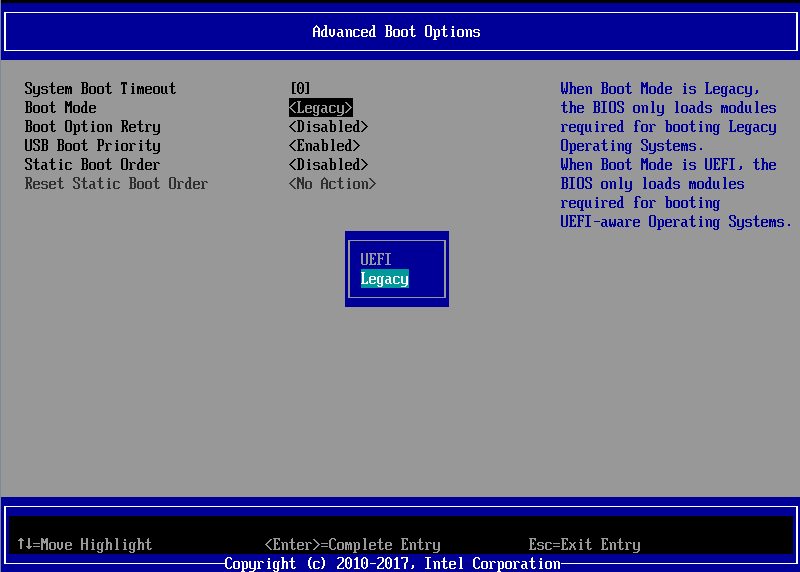
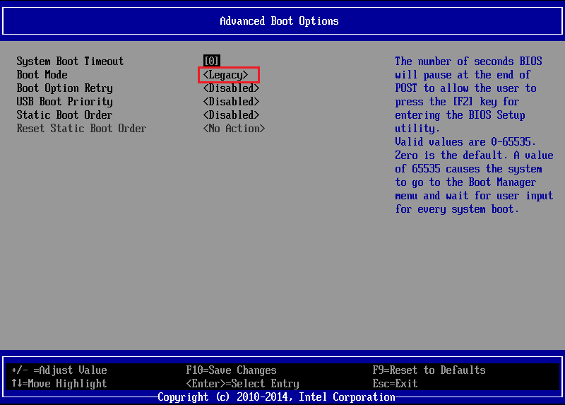
Intel E5 Platforms such as S2600WTTx
Setup > Boot Maintenance Manager > Advanced Boot Options > Boot Mode
- For EFI Mode:
- Under Boot Mode, set this to EFI
- (Depending on the BIOS, if offered, under Use Legacy Video for EFI OS, set this to Enabled)
- For Legacy Mode:
- Under Boot Mode, set this to Legacy
Other Recommended BIOS Settings
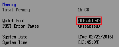
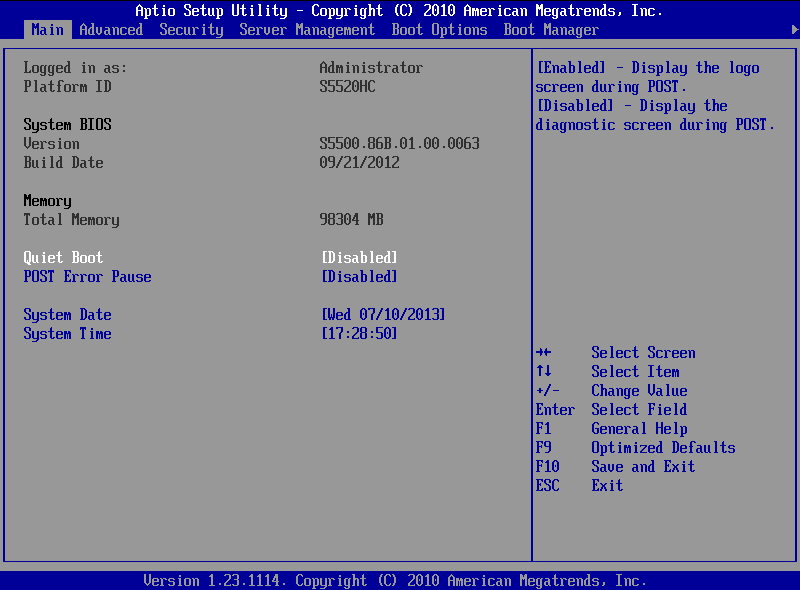
- Disable Quiet boot from the main BIOS. This makes sure you see all of the diagnostic messages as the system starts.
Changing the Quiet Boot BIOS Mode - Intel E3 Platforms such as S1200V3RPL
- This is available on the Main page, which loads as soon as you go into BIOS setup.
- Change Quiet boot to Disabled
Changing the Quiet Boot BIOS Mode - Intel E5 Platforms such as S2600WTTx
- Select Setup Menu, then Main
- Change Quiet boot to Disabled
[Upgrading the Firmware on your RAID Controller]
This is normally done in the factory when your server or workstation was assembled. It may be a good idea to upgrade the firmware on your RAID controller if you are upgrading or reinstalling an older system, especially if you are installing a newer operating system, for example Server 2016 instead of Server 2012R2. In this situation, also consider installing the latest motherboard firmware update package.
Firmware updates are usually easiest done through the EFI Shell.
Contact Stone support for further help.
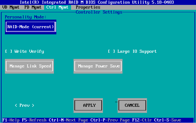
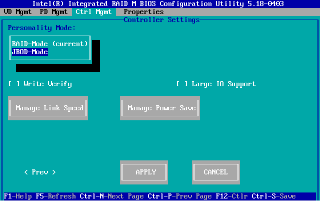
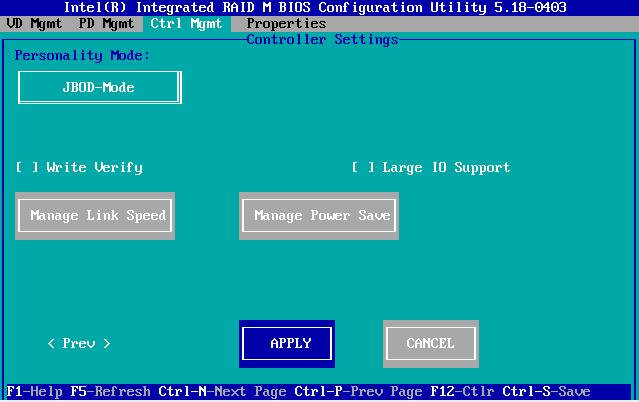
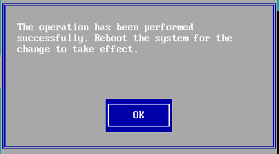
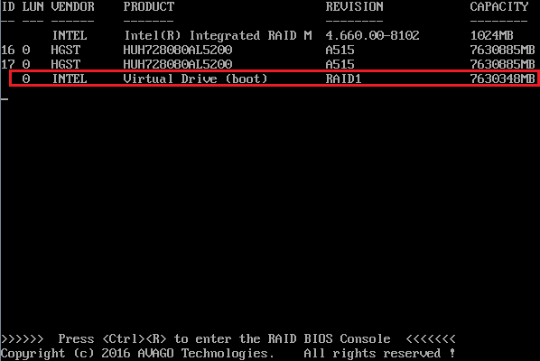
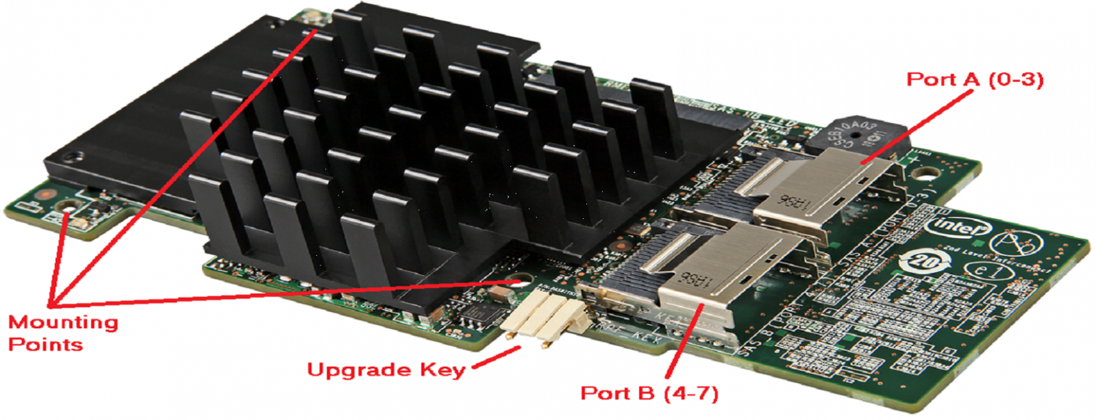
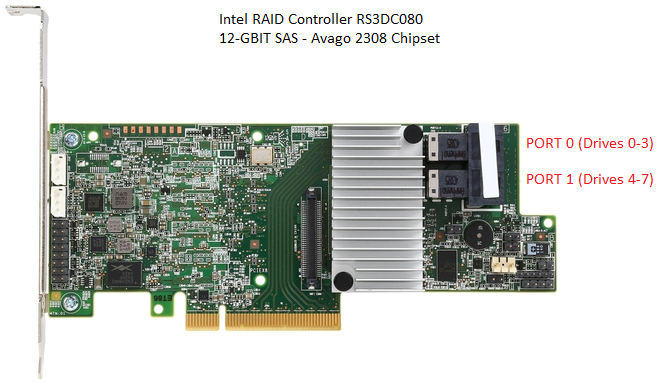
Setup your Boot Volume RAID Array
Again, this is normally done in the factory. However, example steps for creating a RAID 1 Array with two drives for the 12Gbit Series controllers from Intel/Broadcom/LSI are shown below.
- Ensure Quiet Boot is turned off in the Main BIOS
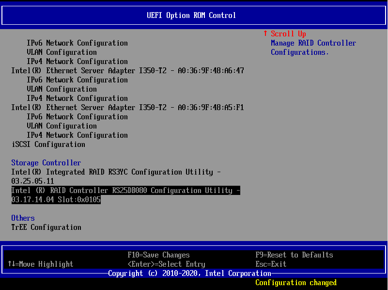
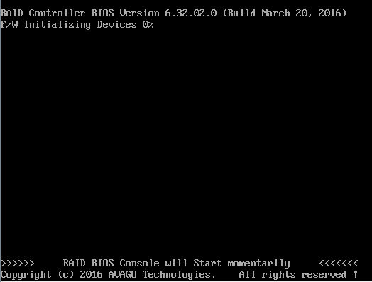
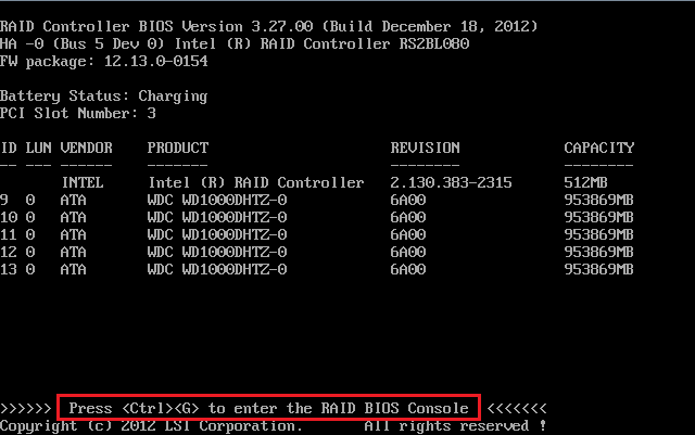
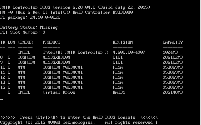
- Use CTRL + R when prompted to go into the RAID BIOS Console (CTRL + G on older controllers)
Note: You might need to turn off UEFI BIOS mode to get access to the RAID BIOS Console, on some systems. If you don't see the option for the RAID BIOS console during POST, turn off EFI Optimised boot / BIOS UEFI mode, complete the work in the RAID BIOS console, and then put the BIOS back to the previous setting.
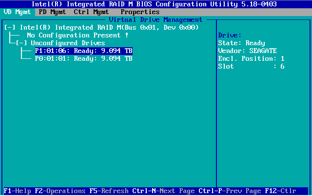
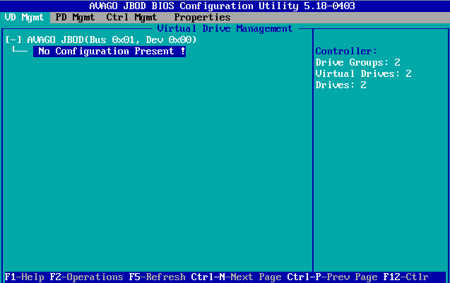
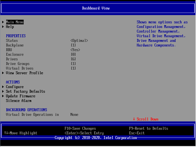
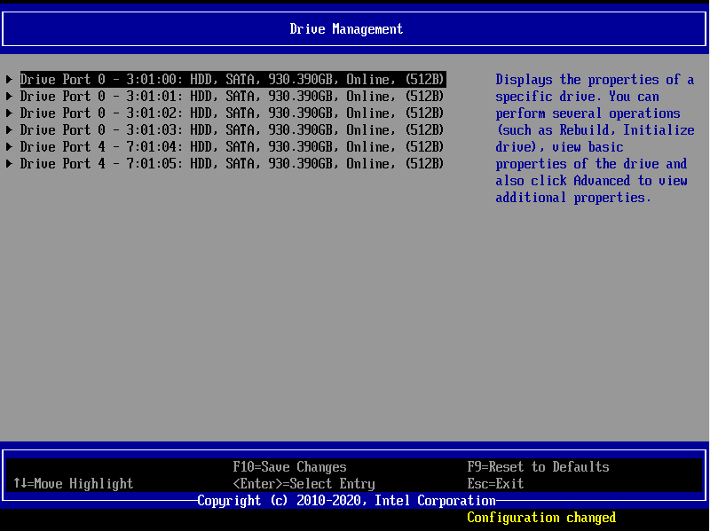
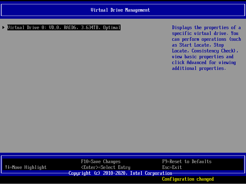
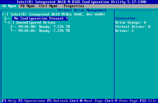
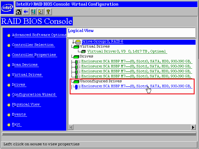
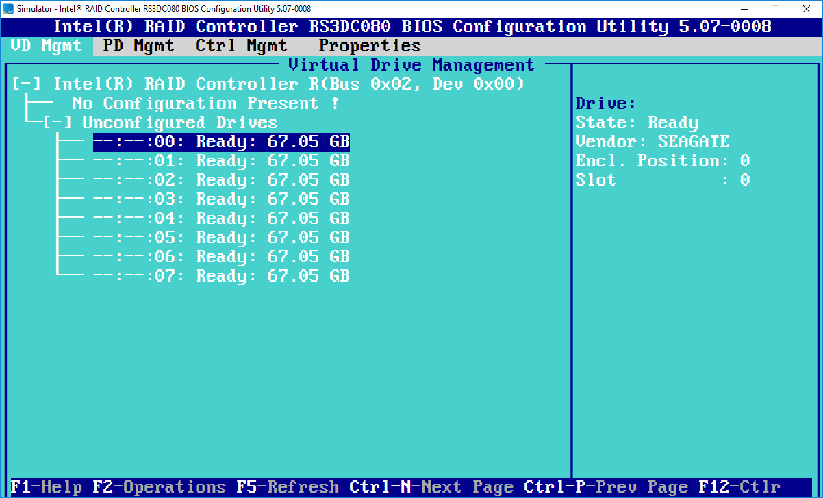
- On the VD Mgmt page, confirm that the are no virtual drives present - look for "No Configuration Present !". The system should also show Virtual Drives: 0 on the right.
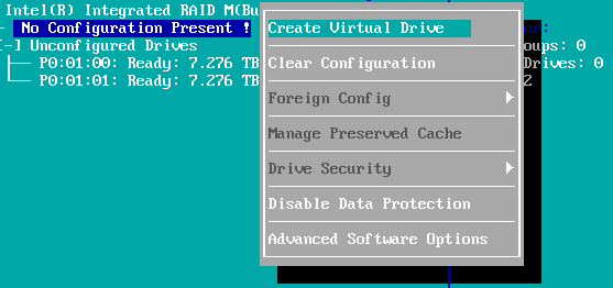
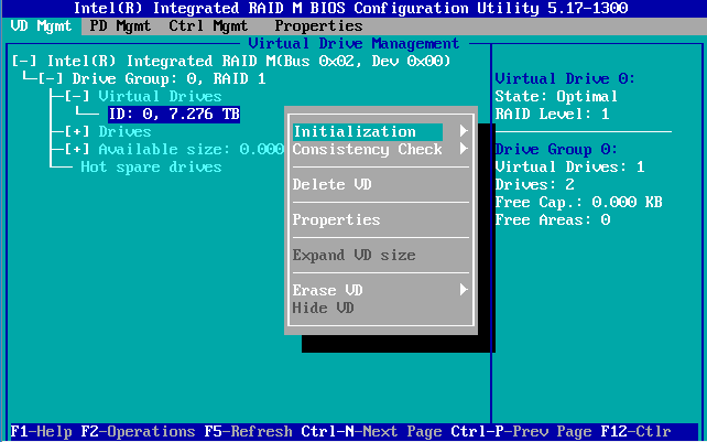
- Whilst the controller, or No Configuration Present is highlighted, press F2 to bring up the operations menu. Then highlight Create Virtual Drive and press Enter.
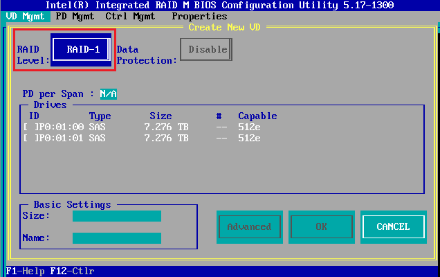
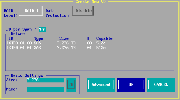
- Under RAID Level, Ensure RAID 1 is selected
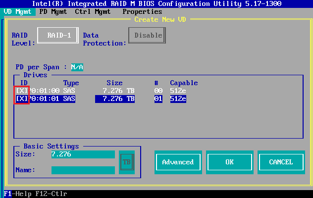
- Use the arrow keys to select the drives one by one. On each drive, use the space bar to add the drive that you want to the array. It should have a cross "X" in the ID checkbox.
- Highlight Advanced and press Enter
- Use the Down Arrow to highlight Initialize
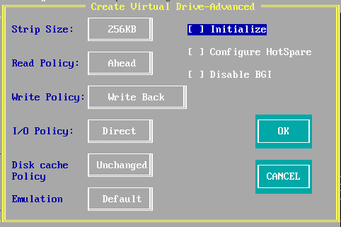
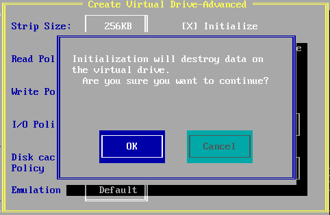
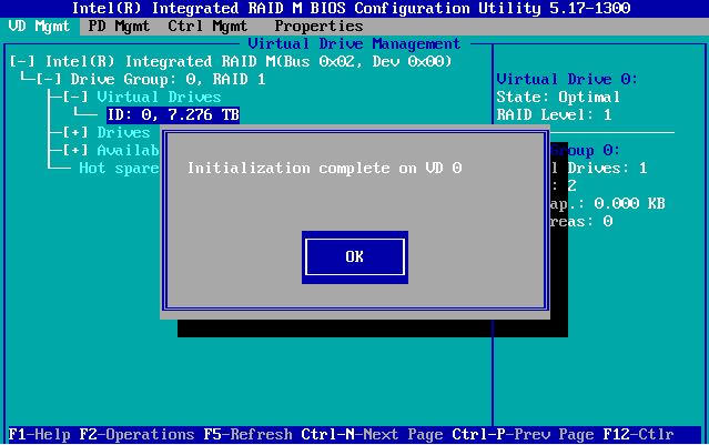
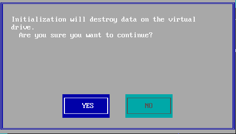
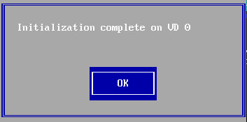
- Press the spacebar to ensure the new virtual drive is initialised when created. Accept the warning message by highlighting OK using the arrow keys, and pressing Enter.
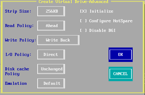
- Highlight OK again (in the Create Virtual Drive-Advanced menu) and press Enter, to accept the configuration.
- Highlight OK on the Create New VD menu, and press Enter.
- Wait for the virtual drive to be initialised. The default is for a fast initialisation, which should take less than a minute irrespective of drive size.
- Press ESC to exit the RAID BIOS console, confirming by highlighting OK and pressing Enter.
Prepare your Installation Media and Boot From It
Ideally, prepare your installation media for direct compatibility with how you intend to use the server.
- If you plan to use UEFI BIOS mode for Windows Server, prepare your installation media for UEFI mode. You may also need to disable Secure Boot.
- If you plan to use Legacy BIOS mode for Windows Server, prepare your installation media for Legacy BIOS MBR mode.
Whereas some tools like ISO2USB produce media that is usually bootable by both UEFI and Legacy mode, this isn't helpful, as you can't be sure which mode the system has booted in.
This is especially important on some server platforms, such as the S1200V3RPL, which support EFI Optimised Mode Enabled (EFI only) and EFI Optimised Mode Disabled (EFI and Legacy support).
Preparing Installation Media for Legacy BIOS
- Set your main BIOS to the correct mode.
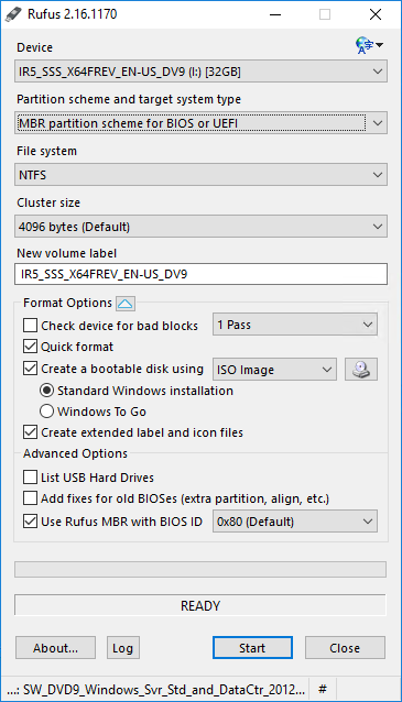
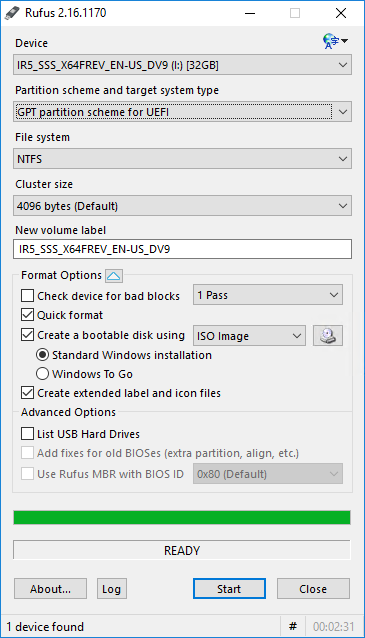
- Use Rufus to prepare your USB pen drive from your installation ISO, and ensure that you select MBR partition scheme for BIOS or UEFI (as this is the closest option)
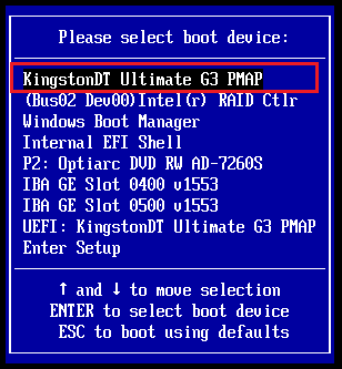
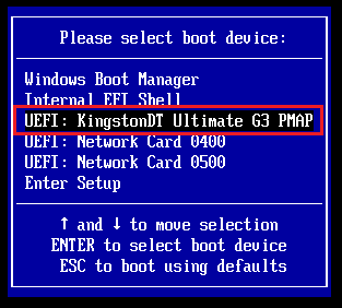
- You must use the F6 Boot Menu option to boot the system from your pen drive and select the non-UEFI option. [Depending on the BIOS, you may be presented with a UEFI boot, which is not what you want when trying to install Windows in Legacy mode].
Tip: Instead of using the F6 boot menu, you can go into the BIOS Setup using F2, and use the Boot Manager menu to select the boot device.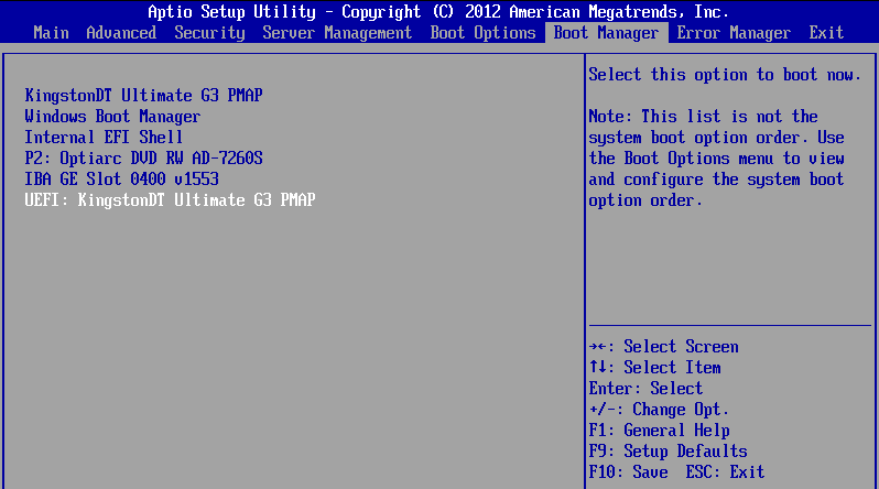
Preparing Installation Media for UEFI BIOS
- Set your main BIOS to the correct mode.
- Temporarily disable Secure Boot in the BIOS.
- Use Rufus to prepare your USB pen drive from your installation ISO, and ensure that you select GPT partition scheme for UEFI.
- BIOS dependant - consider disabling Secure Boot until you have completed Windows setup. Not all Server BIOSes implement Secure boot.
- You should use the F6 Boot Menu option to boot the system from your pen drive and select the UEFI option. [Depending on the BIOS, you may be presented with a non-UEFI boot, which is not what you want when trying to install Windows in UEFI mode].
Tip: ISO2USB is also not suitable for use some quite a lot of modern installation media, such as the latest distributions of Server 2012R2, Windows Server 2016 and Windows 10, because of the size of the files in the sources directory. These files can now be more than 4GB in size, which is greater than the maximum file size permitted by FAT32. ISO2USB only supports FAT32. To get around this issue, use Rufus, as this supports NTFS.
Complete the Installation of Windows
- Setup Windows, suppling the Mass Storage driver if required.
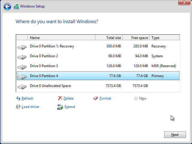
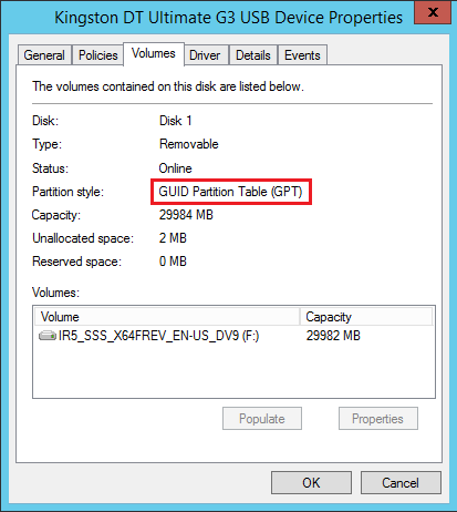
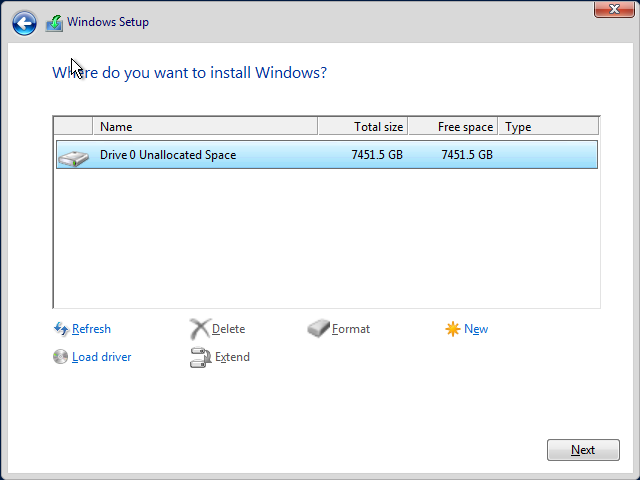
- Example of the Setup disk layout on a UEFI system for GPT partitioning below. An 80GB partition has been created for the installation. Windows Setup automatically creates the other partitions it needs. The remaining 7.3TB will be available for a single large data volume.
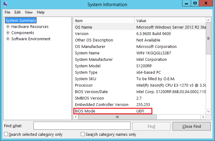
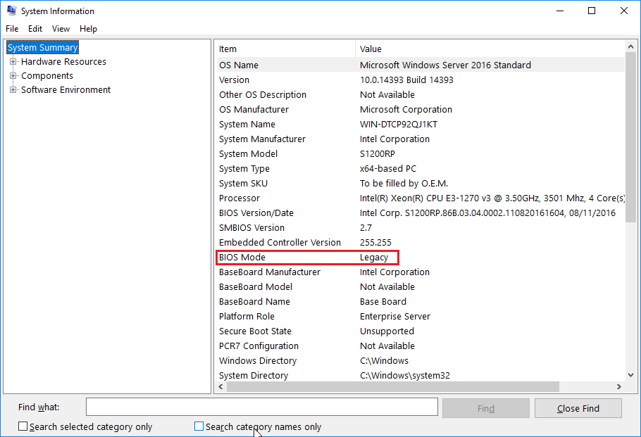
- Once Windows is installed, you can use the MSINFO32 program to confirm that the system is operating in the right BIOS mode.
- If you are using UEFI mode, you may wish to re-enable Secure Boot in the BIOS after the operating system is installed (depending on BIOS availability).
- If you have installed Windows in UEFI mode, you should also be able to use more than 2TB on space on your boot volume, depending on the size of your RAID array.
.PNG)
Installing Updated Drivers and Additional Management Software
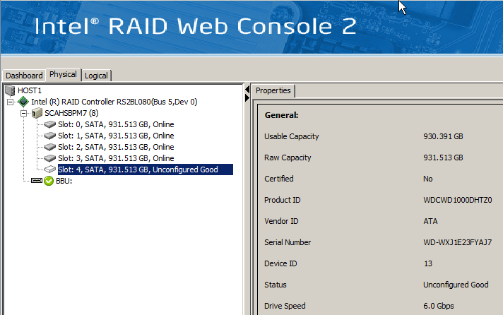
- If you didn't need to load a Mass Storage driver to get Windows installed, you may still benefit from performance and reliability enhancements by installing the latest driver anyway. Some drivers such as Intel/Broadcom/LSI RAID can be updated using Device Manager. Other drivers, such as the Intel RSTe RAID, require you to run the Setup program.
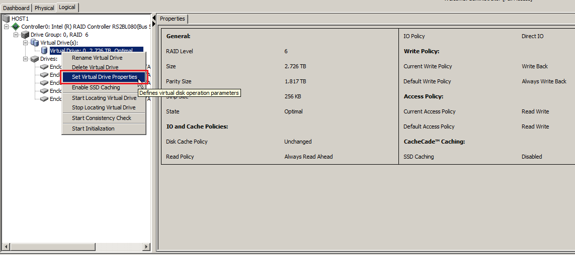
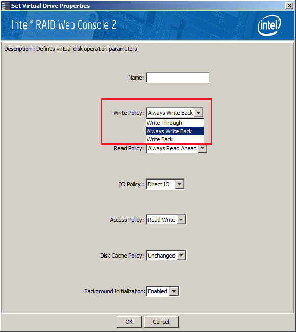
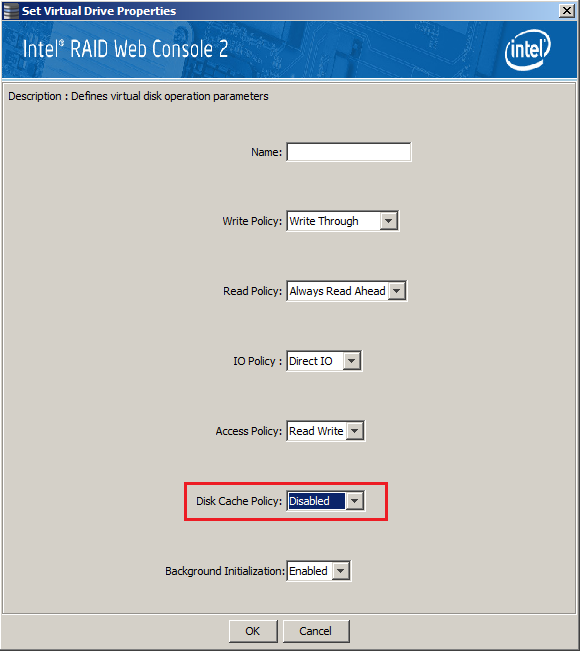
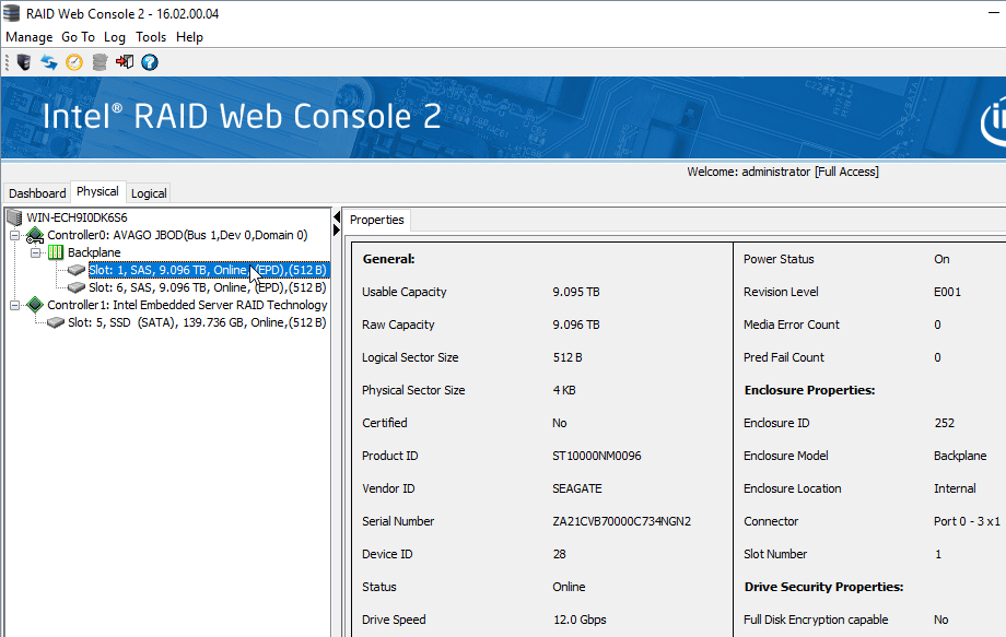
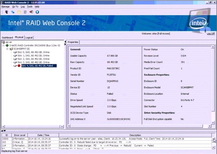
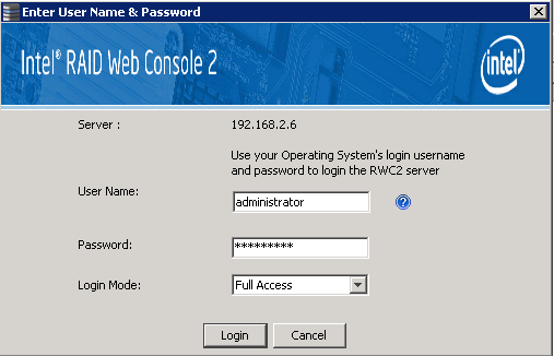
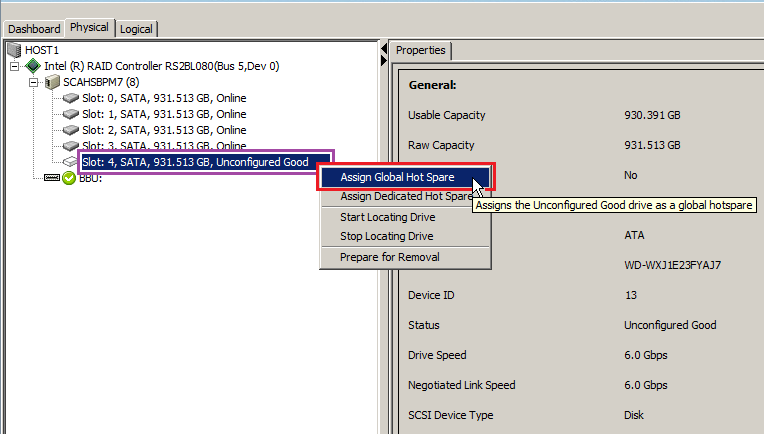
- Again, if you have an Intel/Broadcom/LSI RAID controller or module, it is useful to install the RAID Web Console (Intel) or MegaRAID Storage Manager (Broadcom) software so that you can monitor the RAID array health and setup email alerting.
- Always install the latest Windows updates before putting the server into production use.
Below are some common problems and their solutions. If you are experiencing problems installing Windows on your Stone server or workstation, please do not hesitate to contact Stone support for further help.
I can't Access the RAID BIOS Console any More
- Probable Cause 3: If you see the CTRL + R option to go into the RAID BIOS console, but it is ignored, use the F6 boot menu option after pressing CTRL + R, and then choose the RAID Card BIOS or RAID Card Setup from the list of bootable devices.
I can't Boot the System from my Installation Media
- Probable Cause: Your BIOS must be configured to support the partitioning method on the pen drive.
- Solution 1: Use Device Manager on another PC to check the partitioning method of the volume on the pen drive. If it is partitioned using the GPT method, a BIOS configured for Legacy mode only cannot boot this.
- Solution 2: You may need to turn off Secure boot to enable the booting of some Rufus created pen drives.
I re-created the RAID Array but the Existing Partition Layout or Information is Still There
- Probable Cause: You skipped the initialisation phase when configuring the RAID array.
- Solution: Either create the RAID array again and use the Advanced Creation options > Initialize checkbox, or simply perform a fast initialisation of the existing RAID array. Note that this will delete everything on the virtual disk.
To Perform a RAID Array Fast Initialisation
Note: This procedure will delete everything on the virtual disk. If there is data you need to keep, ensure this is backed up and checked on a completely different virtual disk or controller.
- Press CTRL+R to go into the RAID BIOS Console.
- On the VD Mgmt page, highlight the virtual drive that you want to erase.
- Press F2 to bring up the operations menu.
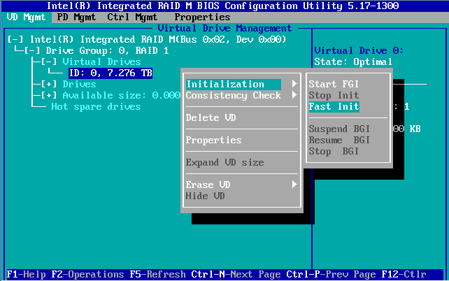
- Choose Initialization, and then Fast Init.
- Accept the warning that you want to destroy the contents of the virtual drive, by highlighting OK and pressing Enter.
- Wait for initialisation to complete. It shouldn't take more than a minute. Use the F5 key to refresh progress.
- Exit the RAID BIOS Console by pressing ESC.
Windows says It Can't be Installed onto the Partition
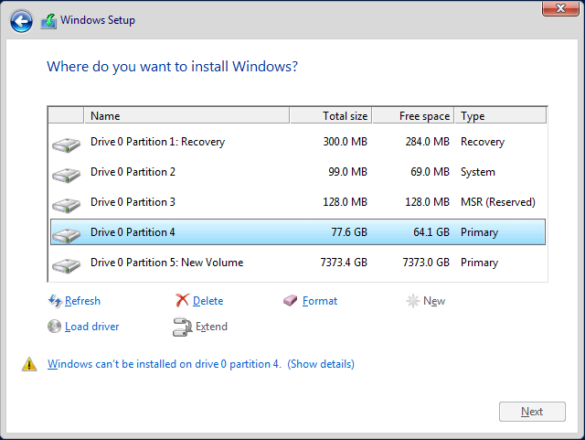
- Probable Cause: The partitioning mode on the disk is incompatible with the mode that you booted the installation media in.
- Solution: Either boot the installation media in opposite BIOS mode, or delete the partitioning information from the disk using Diskpart, or by re-initialising the RAID array. Note that re-initialising the RAID array will delete everything on the array.
Drive 0 is split into More Than One Section of Unallocated Space
- Probable Cause: If your boot disk is larger than 2TB in size, you must use GPT partitioning. GPT partitioning requires UEFI booting.
- Solution:
Note: All of these solutions require reinstalling Windows, and likely, the loss of any data on your boot volume/disk. Backup any data first.
I installed Windows but the RAID Controller is Not Listed As A Bootable Device
- Probable Cause 1: If using UEFI Boot mode, you may not see the RAID Controller as a bootable device.
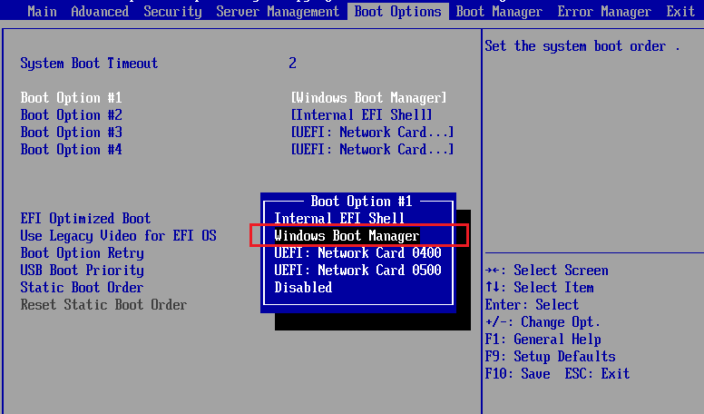
- Solution: When in UEFI mode, the BIOS might not list the RAID Controller as a bootable device. Instead, it detects that a Windows Boot Manager partition exists on the virtual disk, and shows Windows Boot Manager in the BIOS boot order. If using UEFI BIOS mode, check for a Windows Boot Manager option and make sure it is at the top of the boot order.
- Probable Cause 2: Your BIOS isn't set to the right mode when compared to how Windows has been installed.
- Solution:
- If your BIOS is set to EFI Optimised Boot Enabled, or UEFI Boot, then it means that your partitioning is in Legacy MBR mode. Whilst UEFI can boot some MBR partitions, this is less compatible. Follow the solution steps for the problem above.
- If your BIOS is set to Legacy Boot, then it means your partitioning is in GPT mode. Legacy mode BIOS cannot boot GPT partitions.
Using Diskpart to Clear the Disk
Note: This procedure will delete everything on the virtual disk. If there is data you need to keep, ensure this is backed up and checked on a completely different virtual disk or controller.
- After booting from your installation media, get to the stage "Where do you want to install Windows?". This lets you confirm if any Mass Storage drivers are needed - if no Drives are shown, load the Mass Storage driver.
- Press Shift and F10 together to get the setup Command Prompt.
- Type in Diskpart and press Enter
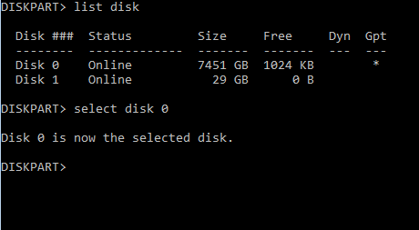
- As the DISKPART prompt, type list disk and press Enter
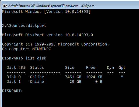
- Note the sizes of the disks. This example also shows that Disk 0 (the 8TB RAID Array) has been formatted using GPT partitioning, whilst the 29GB USB pen drive, containing the installation media, does not. This contributes to why Windows will not install - the installation has been started in Legacy mode, but the disk has been partitioned using GPT, which is only supported using UEFI mode.
- Select the disk to be erased, by typing in select disk and the disk number, for example, select disk 0.
- Use the clean command to remove all partitions, partitioning information and boot signatures.
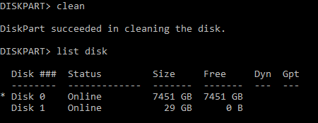
- Close the command prompt.
- In Windows Setup, hit Refresh.
Note: This example shows the removal of GPT partitioning to allow a legacy mode installation to continue. However, as the disk is 8TB in size, in the real world you would want to proceed with a UEFI / GPT installation by making sure your installation media was setup properly and by booting the installation media in the right mode.
The System Boots to the EFI Shell after I Installed Windows
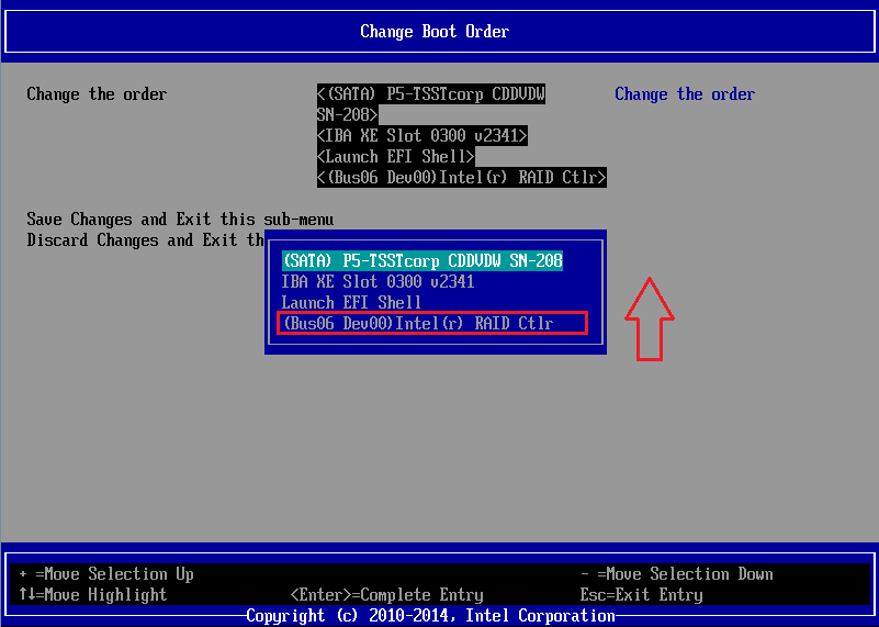
- Probable Cause 1: Incorrect BIOS Boot order
- Solution: Check the BIOS boot order. The EFI Shell should be one of the last BIOS boot entries. Move the Intel RAID controller, or the hard disk, or Windows Boot Manager to be above the EFI Shell in the boot order.
Note: When in UEFI mode, the BIOS might not list the RAID Controller as a bootable device. Instead, it detects that a Windows Boot Manager partition exists on the virtual disk, and shows Windows Boot Manager in the BIOS boot order.
- Probable Cause 2: Missing or offline RAID virtual drive.
- Solution: Check the RAID information displayed during POST to make sure the Virtual Drive is online. If drives or the entire array is missing, check drive seating or cabling.
I have Installed Windows and have my C Drive. But I can't make the D data Drive fill the rest of the Drive.
- Probable Cause: If you can't make the C drive go beyond 2TB, or cannot create a second data volume in the unallocated space on disk 0, the system has been installed with an MBR boot volume, and the system is likely running in Legacy mode.
.PNG)
- Solution:
- Use MSINFO32 to confirm the BIOS boot mode.
I enabled EFI Optimised Boot / UEFI boot, and can no longer get into the main BIOS Setup using F2.
- Probable Cause: Your motherboard BIOS does not correctly support your RAID controller.
- Solution:
- As a temporary fix, turn off or shutdown the system, disconnect all the disks from the system, ideally by sliding them out by a few centimetres. This ensures you can put them back and reconnect them in the same order. Turn the system on to gain access to the BIOS.
- Check for an updated motherboard BIOS firmware.
- Check for updated RAID controller firmware.
- Be careful about changing the BIOS EFI Optimised / UEFI boot mode to Legacy, as this may prevent your operating system from booting. If you need to make the change to complete firmware updates, put the BIOS settings back before then attempting to boot Windows again.
I Deleted the device EFI Boot Option from the BIOS, How Can I add this Back In?
- Problem: You deleted an EFI Boot option from the BIOS, and the system no longer starts Windows.
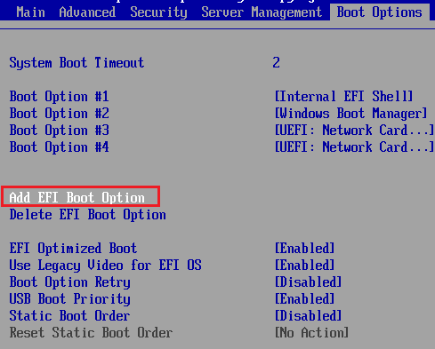
- Solution: Use the Add EFI Boot Option facility.
Adding an EFI Boot Option
This allows you to specify a bootable EFI device, useful if you have changed your motherboard or otherwise lost your boot entries.
- Go into the BIOS using F2.
- Choose the option to Add an EFI Boot Entry
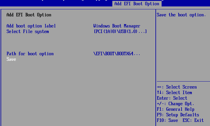
- Add the boot option label, for example, Windows Boot Manager.
- Select the File System - you should see the an Intel RAID Controller as a PCI device, alternatively you will also be able to select any available USB devices here.
- Add in the Path for Boot Option - this is normally \EFI\BOOT\BOOTX64.EFI for x64 Windows.
- Select Save to Add the entry.
Tip: If you don't have the option in your BIOS for "Add EFI Boot Option", then either your motherboard is in Legacy mode, or all available EFI bootable devices are already added as boot options.
Applies to:
- Stone Server and Workstation Products.
.PNG)
.png)